Method and module for controlling a vehicle's speed

a technology a method, applied in adaptive control, process and machine control, instruments, etc., can solve the problems of different demand for processor capacity for determining the reference speed, vehicle acceleration, fuel-expensive way of running the vehicle, etc., and achieve the effect of reducing processor costs and constant load on the processor

Inactive Publication Date: 2013-04-04
SCANIA CV AB
View PDF3 Cites 16 Cited by
  • Summary
  • Abstract
  • Description
  • Claims
  • Application Information

AI Technical Summary

Benefits of technology

[0023]The method described results in a substantially constant load upon the processor, since the same number of predictions are made during each simulation cycle at a constant frequency. The processor load is independent of the power output of the vehicle's engine, the weight of the vehicle and the topography of the route. The processor concerned thus knows how much processor capacity will be needed, which is therefore consistently allocated. The processor load will thus be the same in different situations of changing topology and be independent of the vehicle's engine torque. It is thus also possible for the processor concerned to be dimensioned without having to cater for any extreme worst scenarios but rather to cater for uniform processor load. The processor cost can thus be reduced.

Problems solved by technology

This sometimes results in the vehicle accelerating over the crest of a hill and potentially into a subsequent downgrade on which it has then to be braked to avoid exceeding the set speed, which is a fuel-expensive way of running the vehicle.
However, the topography of the carriageway, the weight of the vehicle and the performance of the engine may result in differences in demand for processor capacity for determining the reference speed.
The processor incorporated in the system will therefore be subject to relatively large demands, since the load upon the processor may vary greatly from situation to situation.

Method used


Image

  • Method and module for controlling a vehicle's speed
  • Method and module for controlling a vehicle's speed
  • Method and module for controlling a vehicle's speed

Examples


Embodiment Construction

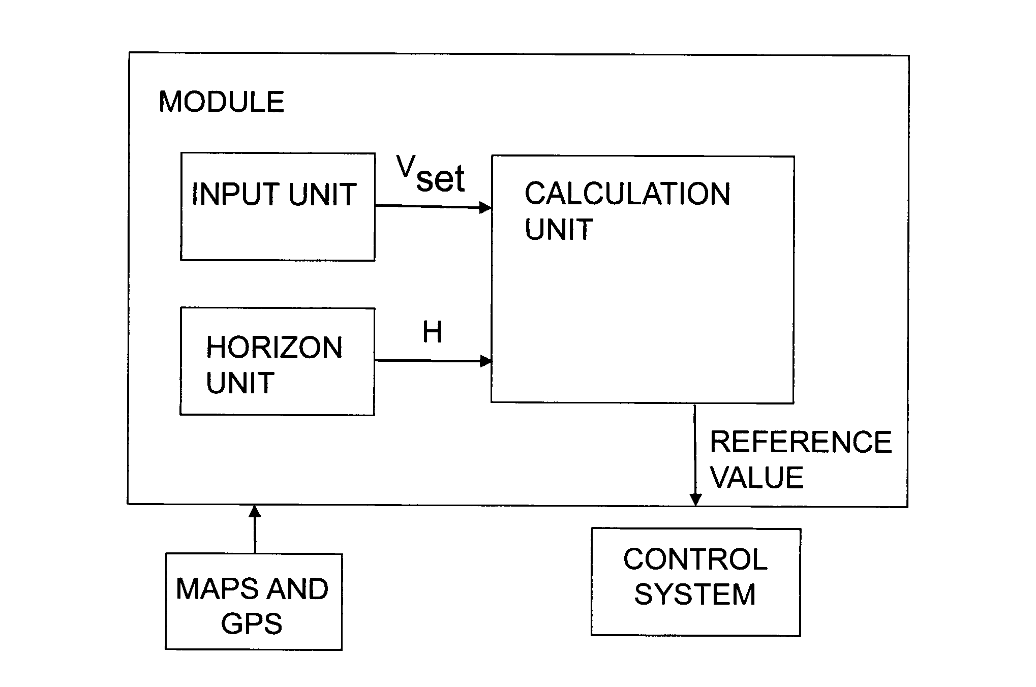
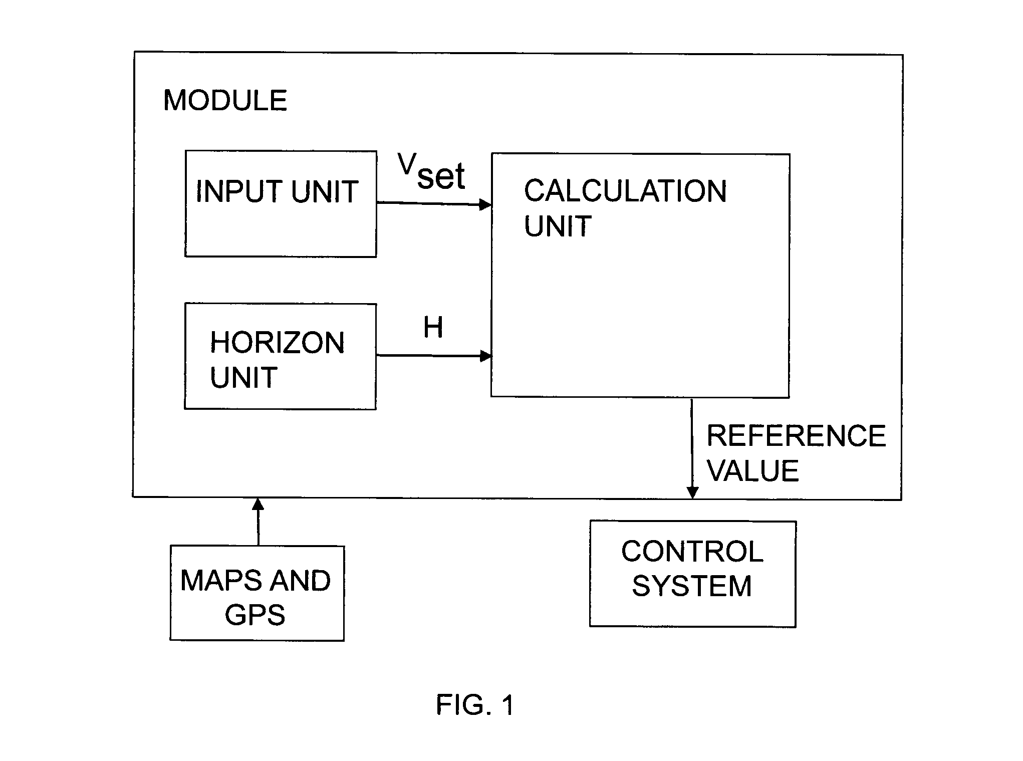
[0034]FIG. 1 depicts a module for controlling a vehicle's speed according to an embodiment of the invention. The module comprises an input unit adapted to receiving a desired speed vset for the vehicle. The driver may for example set a desired speed vset which he / she wishes the vehicle to maintain. The module comprises also a horizon unit adapted to determining a horizon for the intended itinerary by means of map data and location data. The horizon is made up of route segments with at least one characteristic for each segment. An example of a segment's characteristics might be its gradient a in radians.

[0035]In the description of the present invention, GPS (Global Positioning System) is indicated for determining location data for the vehicle, but it should be appreciated that other kinds of global or regional positioning systems are also conceivable to provide the vehicle with location data, e.g. systems which use a radio receiver to determine the vehicle's location. The vehicle may...


PUM


Abstract

A method for controlling a vehicle's speed by adopting a desired speed vset for the vehicle; determining a horizon for the intended itinerary made up of route segments, effecting the following during each of a number of simulation cycles (s) each comprising a number N of simulation steps conducted at a predetermined frequency f: first predicting the vehicle's speed vpred<sub2>—</sub2>cc along the horizon with conventional cruise control when vset is presented as reference speed, comparing the predicted vehicle speed vpred<sub2>—</sub2>cc in a range vmin to vmax, making a second prediction of the vehicle's speed vpred<sub2>—</sub2>Tnew along the horizon based on the vehicle's engine torque T; determining a reference value for how the vehicle's speed is to be influenced on the basis of at least one of the comparisons and the predicted vehicle speed vpred<sub2>—</sub2>Tnew; controlling the vehicle by the reference value. A module for the foregoing controls a vehicle's speed.

Description

FIELD OF THE INVENTION[0001]The present invention relates to a method and a module for controlling a vehicle's speed on the basis of its predicted speed according to the introduction to the independent claims.BACKGROUND TO THE INVENTION[0002]Today's traditional cruise controls maintain a constant reference speed which is usually set by the driver. The value of the reference speed is only altered when the driver him / herself adjusts it while driving. The reference speed is then passed to a control system which controls the vehicle in such a way that, if possible, the vehicle maintains the reference speed. If the vehicle is equipped with an automatic gear change system, its gears change so that it can maintain desired speed.[0003]When cruise control is used in hilly terrain, the cruise control system will try to maintain set speed both uphill and downhill. This sometimes results in the vehicle accelerating over the crest of a hill and potentially into a subsequent downgrade on which it...

Claims


Application Information

Patent Timeline
Patent Type & Authority Applications(United States)
IPC IPC(8): B60K31/00
CPCB60W30/143B60W50/087B60W2550/143B60K31/00B60W2720/103Y02T10/84B60W2550/402B60W50/0097B60W2552/20B60W2556/50B60W30/14B60W2050/0001B60W2552/15G05B13/04
Inventor JOHANNSSON, OSKARSODERGREN, MARIAROOS, FREDRIK
Owner SCANIA CV AB
Why Eureka
Try Eureka