
Voice communication system encoding and decoding voice and non-voice information

a communication system and voice technology, applied in the field of voice communication system, can solve the problems of significant deterioration of voice communication quality, difficulty in ensuring the quality of voice communication, and damage to original information by embedding additional information, so as to minimize the deterioration of sound quality and maximize communication bandwidth.

Inactive Publication Date: 2013-04-04
OKI ELECTRIC IND CO LTD
View PDF4 Cites 9 Cited by
  • Summary
  • Abstract
  • Description
  • Claims
  • Application Information

AI Technical Summary

Benefits of technology

The present invention is a voice communication system that reduces sound quality degradation when transmitting a code stream with additional information embedded. The system controls the information embedding positions based on the background noise characteristic of the signal stream. This results in minimized sound quality degradation and efficient use of communication bandwidth when transmitting codes with additional information embedded.

Problems solved by technology

Although the information-embedded packet transmissions are so useful, it is disadvantageous in that original information may be damaged by embedding additional information.
When original information to be transmitted is voice, this issue becomes particularly important.
Because, part of voice waveforms or some parameters is possibly overwritten by additional information so as to affect the sound quality, rendering the quality of voice communication considerably deteriorating.
Therefore, the conventional systems of embedding additional information at predetermined positions regardless of the noise characteristics raise the problem that deterioration in sound quality increases more than expected by the designers of the systems.

Method used


Image

  • Voice communication system encoding and decoding voice and non-voice information
  • Voice communication system encoding and decoding voice and non-voice information
  • Voice communication system encoding and decoding voice and non-voice information

Examples


Embodiment Construction

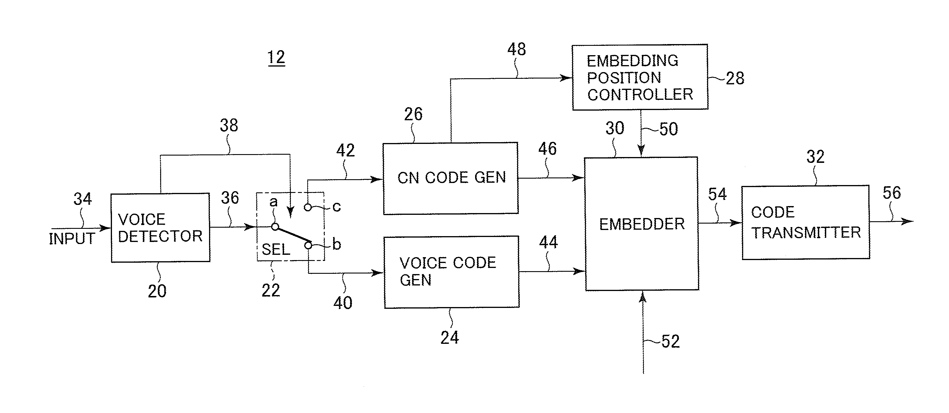
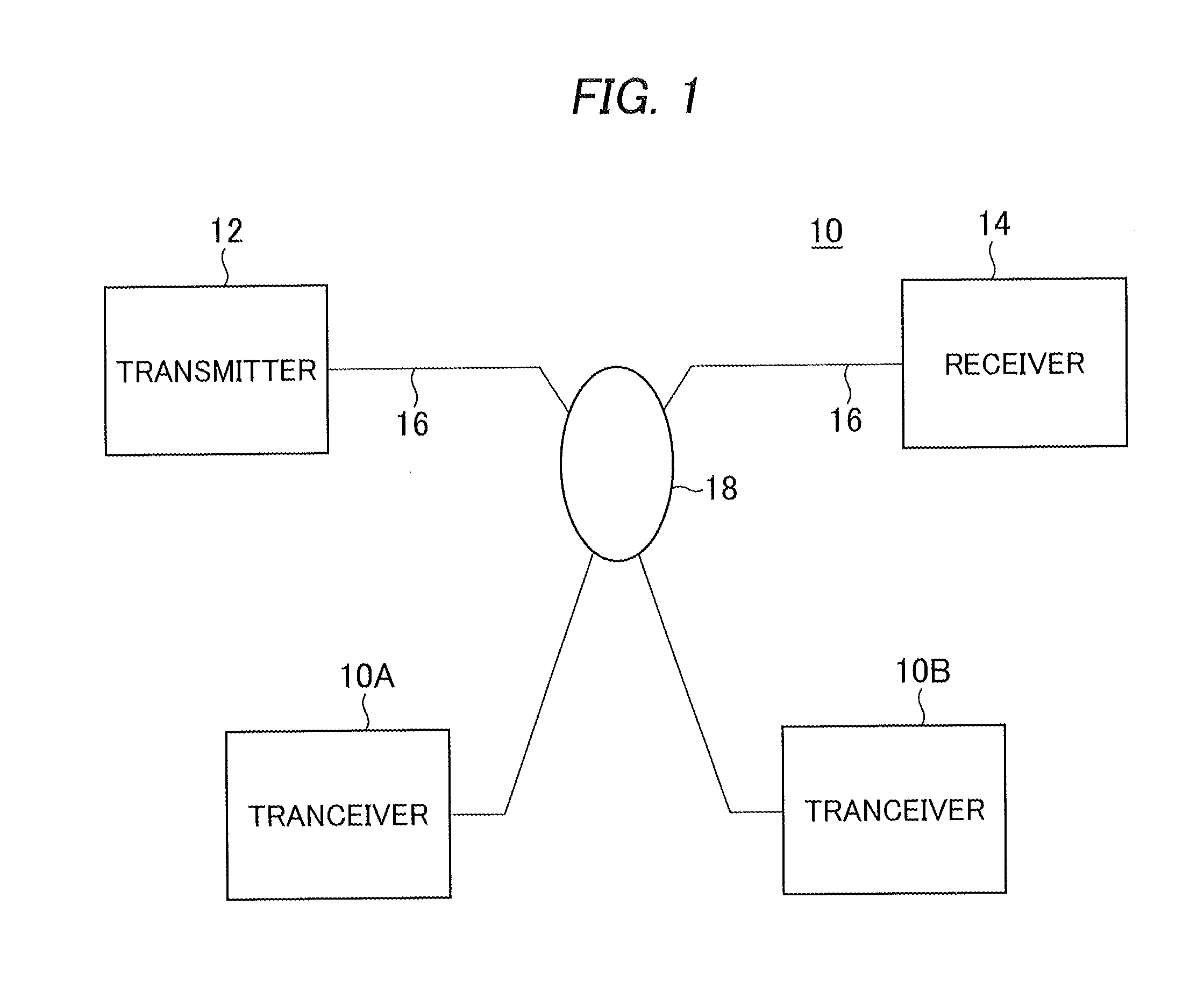
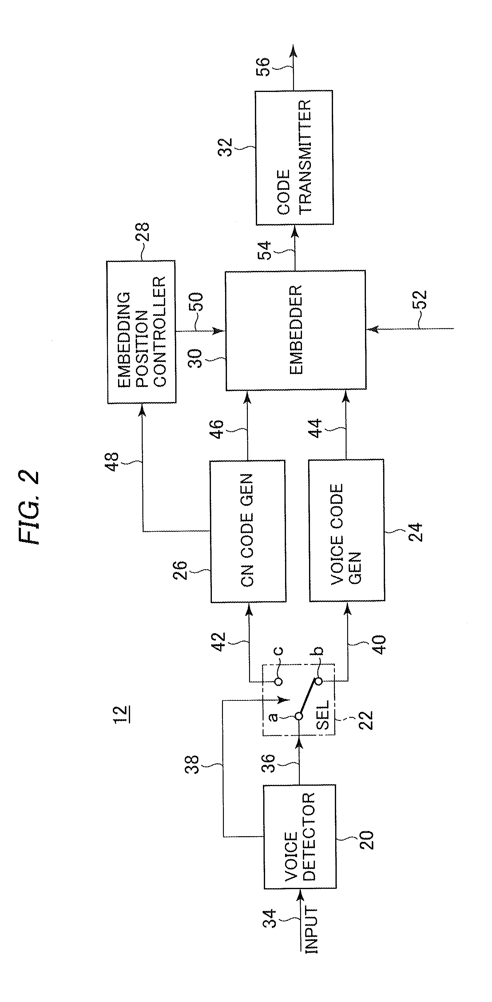
[0024]Preferred embodiments of a voice communication system according to the present invention will be described in detail with reference to the accompanying drawings. Referring first to FIG. 1, a preferred embodiment of the voice communication system according to the invention is generally designated with a reference numeral 10. The voice communication system 10 includes a transmitter 12 including the function of voice encoder, a receiver 14 including a function of voice decoder, and transmitter-receivers 10A and 10B, which are interconnected to a telecommunications network 18. The configurations of the transmitter 12 and receiver 14 are shown more particularly in FIGS. 2 and 7, respectively.

[0025]The transmitter 12 is generally adapted such that when an input signal 34, FIG. 2, is from a voice section of a signal stream to be transmitted it is used to generate a voice code and when the input signal 34 is from a background noise section of the steam it is used to extract a noise fe...


PUM


Abstract

In a voice coding apparatus of a voice communication system, feature parameters of background noise in background noise sections of an input signal stream are extracted and background noise is encoded into a comfortable-noise code, and embedding positions where additional information is to be embedded are determined according to the values of the extracted feature parameters. Additional information is embedded into the embedding positions thus determined of the voice or comfortable-noise code, which will be transmitted to a voice decoding apparatus in the system. In the decoding apparatus, the transmitted code is separated into voice and background noise sections to be decoded. From the background noise sections, the values of the feature parameters are found out and used to reference a correspondence relationship table to determine the embedding positions where the additional information is embedded. The additional information is extracted at the embedding positions thus determined to be restored.

Description

BACKGROUND OF THE INVENTION[0001]1. Field of the Invention[0002]The present invention relates to a voice communication system, and more in particular to a voice communication system for encoding voice and voice-related information including non-voice information with the non-voice information embedded and for decoding the voice and encoded voice-related information.[0003]2. Description of the Background Art[0004]In recent years, telecommunications systems have been developed which allow a larger amount of information to be transmitted while preventing the load on the communication lines from increasing. In order to implement such large-capacity information transmission, for example, packet communications systems may be adapted not only to assemble voice packets of telephonic speech signals but also to divide data of data files into file segments to embed the data of the file segments in the voice packets, which will in turn be received and disassembled on a receiving side into voice...

Claims


Application Information

Patent Timeline
Patent Type & Authority Applications(United States)
IPC IPC(8): G10L19/00
CPCG10L19/012G10L25/84G10L19/018
Inventor TAKAHASHI, KATSUYUKI
Owner OKI ELECTRIC IND CO LTD
Learn More