Submerged combustion glass manufacturing systems and methods

a manufacturing system and technology of glass, applied in glass furnace equipment, glass melting equipment, manufacturing tools, etc., can solve the problems of molten glass carryover into the melter exhaust, reducing exhaust flow, and reducing the flow of exhaust ducts, so as to reduce the fluctuation of melter pressure and/or carryover

Active Publication Date: 2013-04-11
JOHNS MANVILLE CORP
View PDF4 Cites 79 Cited by
  • Summary
  • Abstract
  • Description
  • Claims
  • Application Information

AI Technical Summary

Benefits of technology

[0007]In accordance with the present disclosure, submerged combustion melters and methods...

Problems solved by technology

Submerged combustion melters and their operation may cause exhaust pressure and exhaust volume fluctuations due to large bubbles of gas from submerged combustion burners, which may lead to...

Method used


Image

  • Submerged combustion glass manufacturing systems and methods
  • Submerged combustion glass manufacturing systems and methods
  • Submerged combustion glass manufacturing systems and methods

Examples


embodiment 100

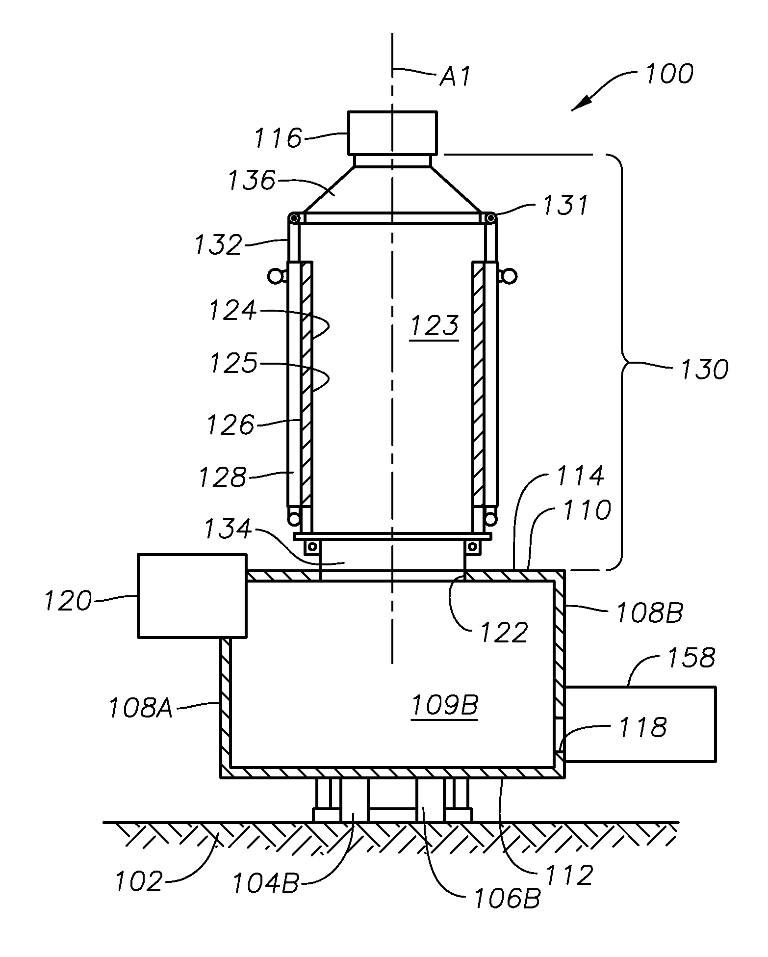
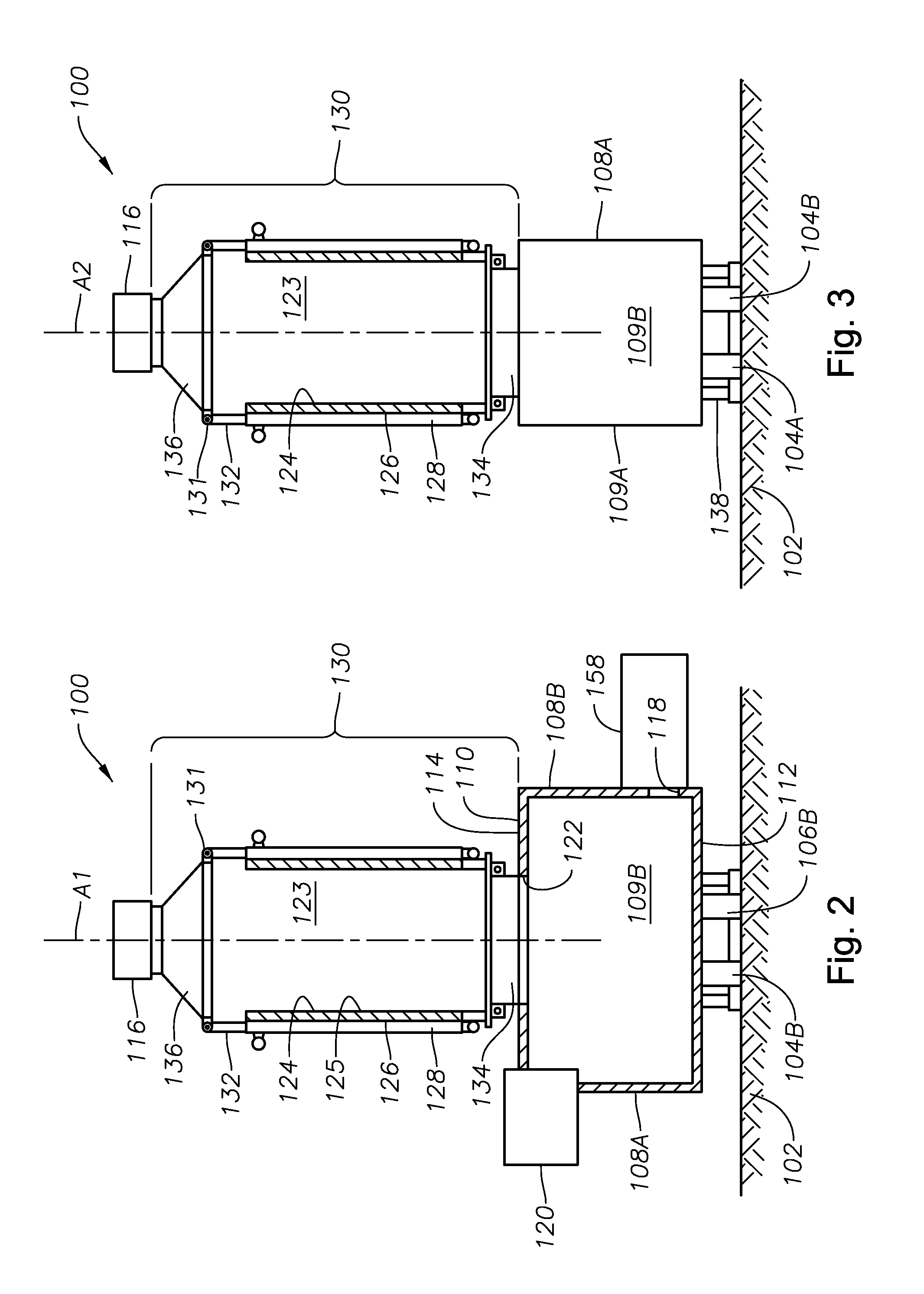
[0069]FIGS. 2 and 3 are side elevation and end elevation views, respectively, partially in cross-section, of a system embodiment 100 in accordance with the present disclosure, including a glass tank furnace or melter 110 positioned on a plant floor or other surface 102, including four burners 104A, 104B, 106A, and 106B (burner 106A is hidden in these views), one or more of which may be of the adjustable burner type described in assignee's co-pending U.S. patent application Ser. No. ______, filed ______ (JM 8054), comprising first and second conduits configured to form a primary annulus between the external surface of the first conduit and the internal surface of the second conduit, and an adjustable structure comprising a generally cylindrical central hub adjustable axially in relation to and removably attached to the first end of the first conduit, the hub defining a central passage and one or more non-central through passages. More than or less than two burners may be used, as wel...

embodiment 200

[0074]FIG. 5 is a more detailed schematic perspective view of a portion of the exhaust structure of the melter and system embodiment of FIG. 4, illustrating in more detail cooling panels 228B and 240B, each having three vertical flow-though sections separated by partitions 228C, 228D, 240C, and 240D. Cooling panels 228 and 240 have air inlets generally noted at 246 and air outlets generally noted at 248. Also viewable in FIG. 5 is metal panel 226 (Inconel in embodiment 200), while refractory lining 224 is shown schematically in the plan view of FIG. 6 of the structure illustrated in FIG. 5.

[0075]Melter and system embodiments 100 and 200, as well as other melters, systems, and methods in accordance with the present disclosure, may process a full range of glass compositions and batch materials including commercial borosilicate and soda-lime glasses, as well as compositions for commercial mineral and stone wools. The melter dimensions and the number of submerged combustion burners may ...


PUM

PropertyMeasurementUnit
Temperatureaaaaaaaaaa
Areaaaaaaaaaaa
Levelaaaaaaaaaa

Abstract

Submerged combustion glass manufacturing systems include a melter having a floor, a roof, a wall structure connecting the floor and roof, and an exhaust passage through the roof. One or more submerged combustion burners are mounted in the floor and/or wall structure discharging combustion products under a level of material being melted in the melter and create turbulent conditions in the material. The melter exhausts through an exhaust structure connecting the exhaust passage with an exhaust stack. The exhaust structure includes a barrier defining an exhaust chamber having an interior surface, the exhaust chamber having a cross-sectional area greater than that of the exhaust stack but less than the melter. The barrier maintains temperature and pressure in the exhaust structure at values sufficient to substantially prevent condensation of exhaust material on the interior surface.

Description

CROSS-REFERENCE TO RELATED APPLICATIONS[0001]This application is related to assignee's U.S. non-provisional patent application Ser. No. 12 / 817,754, filed Jun. 17, 2010, and Ser. No. 12 / 888,970, filed Sep. 23, 2010, both of which are incorporated herein by reference. This application is also related to assignee's Attorney Docket Nos. 8054 and 8062, filed on even date herewith, both of which are incorporated herein by reference.BACKGROUND INFORMATION[0002]1. Technical Field[0003]The present disclosure relates generally to the field of submerged combustion glass melters and methods of use.[0004]2. Background Art[0005]Submerged combustion melters are known for producing molten glass. Submerged combustion melters and their operation may cause exhaust pressure and exhaust volume fluctuations due to large bubbles of gas from submerged combustion burners, which may lead to batch (starting material) carryover and / or molten glass carryover into the melter exhaust. Carryover may lead to reduce...

Claims


Application Information

Patent Timeline
IPC IPC(8): C03B5/235C03B5/42C03B5/183
CPCC03B5/167C03B5/2356C03B2211/22C03B5/2353C03B5/237C03B5/183C03B5/193C03B2211/23C03B2211/40
Inventor HUBER, AARON MORGANMARTIN, MARLON KEITH
Owner JOHNS MANVILLE CORP
Why Eureka
Try Eureka