Hydrogen Storage System

a technology of hydrogen storage and storage tanks, which is applied in the direction of gas/liquid distribution and storage, containers, packaging goods types, etc., can solve the problems of reducing the overall usefulness of the vehicle, the size of the hydrogen tank is impractically large, and the space allocated for the hydrogen tank or the available space in the vehicle is difficult to install, so as to reduce the stress, reduce the stress, and reduce the effect of tensile strength and stiffness

Inactive Publication Date: 2013-04-18
ALSET IP SARL
View PDF14 Cites 17 Cited by
  • Summary
  • Abstract
  • Description
  • Claims
  • Application Information

AI Technical Summary

Benefits of technology

[0011]The present invention provides a Hydrogen storage system comprising N storage elements coupled to each other to form one or more containers that occupy or fit within boundaries of a defined space with boundaries, dimensions, and shape resulting in a volume V where N is an integer equal to 2 or greater. Each of the storage elements has a volume that is a fraction of (or substantially less than) the volume V resulting in each storage element and the one or more containers having reduced dimensions compared to the dimensions of the defined space of volume V. A fraction of the volume V refers to a volume of space occupied by one of N storage elements such that all N storage elements fit within the boundaries of the defined space of volume V. Because each of the storage elements has a volume that is substantially less than the overall volume V, the inner surfaces of each of the storage elements experience substantially less stress compared to the stress experienced by inner surfaces of one storage tank of volume V. That is, the volume of each of the storage elements is reduced to a value that allows usage of less costly but adequately strong fibers in the construction of such storage elements. As a result, the reduced stress experienced by the inner surfaces of each of the storage elements allows the usage of fiber material (e.g., Innegra, Basalt or other fiber having similar such properties) having relatively lower tensile strength and stiffness in the construction of each such storage element thus reducing the cost of the storage system.

Problems solved by technology

In particular, the size, cost of manufacture, and weight of hydrogen tanks are issues that complicate the design and practicability of such tanks Also, the storage mass of the Hydrogen is itself a key consideration.
A first issue is the size of the tanks relative to the space allocated to them in vehicles.
At a pressure in the range of 200-350 bars, the amount of Hydrogen needed to be stored in a Hydrogen tank to be comparable to the energy content of a conventional gasoline tank often makes the size of the Hydrogen tank impractically large and in many cases impossible to install in the space allocated for the tank or in available space in the vehicle.
Often the only available space is the trunk of an automobile and in many cases the size of a 200-350 bar tank would, for many vehicles, use virtually the entire trunk space reducing the overall usefulness of the vehicle.
The fibers used to construct the tanks are usually relatively strong fibers (such as carbon fibers), which have the requisite amount of tensile strength and stiffness to withstand the stresses resulting from relatively large diameter dimensions of the tanks The issue with these relatively strong fibers is their cost.
Carbon fibers and other fibers with comparable physical characteristics are relatively very expensive and thus the costs of manufacture of conventional hydrogen tanks are accordingly expensive.
With increasing pressure comes the need for strong fibers, which as described above makes the costs of such tanks relatively expensive.
Also, in many cases the cost of manufacturing such thicker wall tanks increases due to the extra cost of additional wall material and modification in the manufacturing process for these tanks.

Method used


Image

  • Hydrogen Storage System
  • Hydrogen Storage System
  • Hydrogen Storage System

Examples


first embodiment

[0039]In the storage system of the present invention, all of the storage elements may be coupled to each other to form one or more containers positioned proximate each other within the boundaries of the defined space of volume V where the containers may be different in size, shape and architecture or they may all be the same in size, shape and architecture.

second embodiment

[0040]In the storage system of the present invention, the storage elements may be coupled to each other to form one or more containers each of which is positioned within the boundaries of the defined space of volume V. Additionally, one or more other containers—not formed from storage elements—can also be positioned within the boundaries of the defined space of volume V. The containers formed from storage elements and containers not formed from the storage elements all fit within the boundaries of the defined space of volume V.

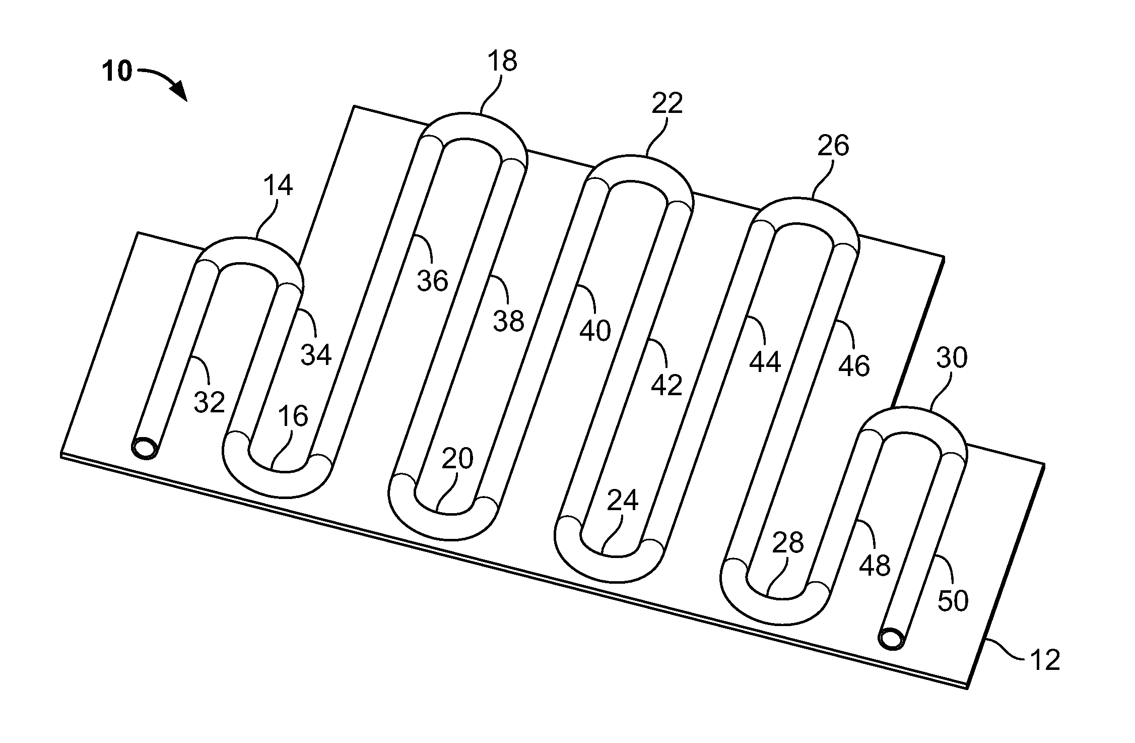
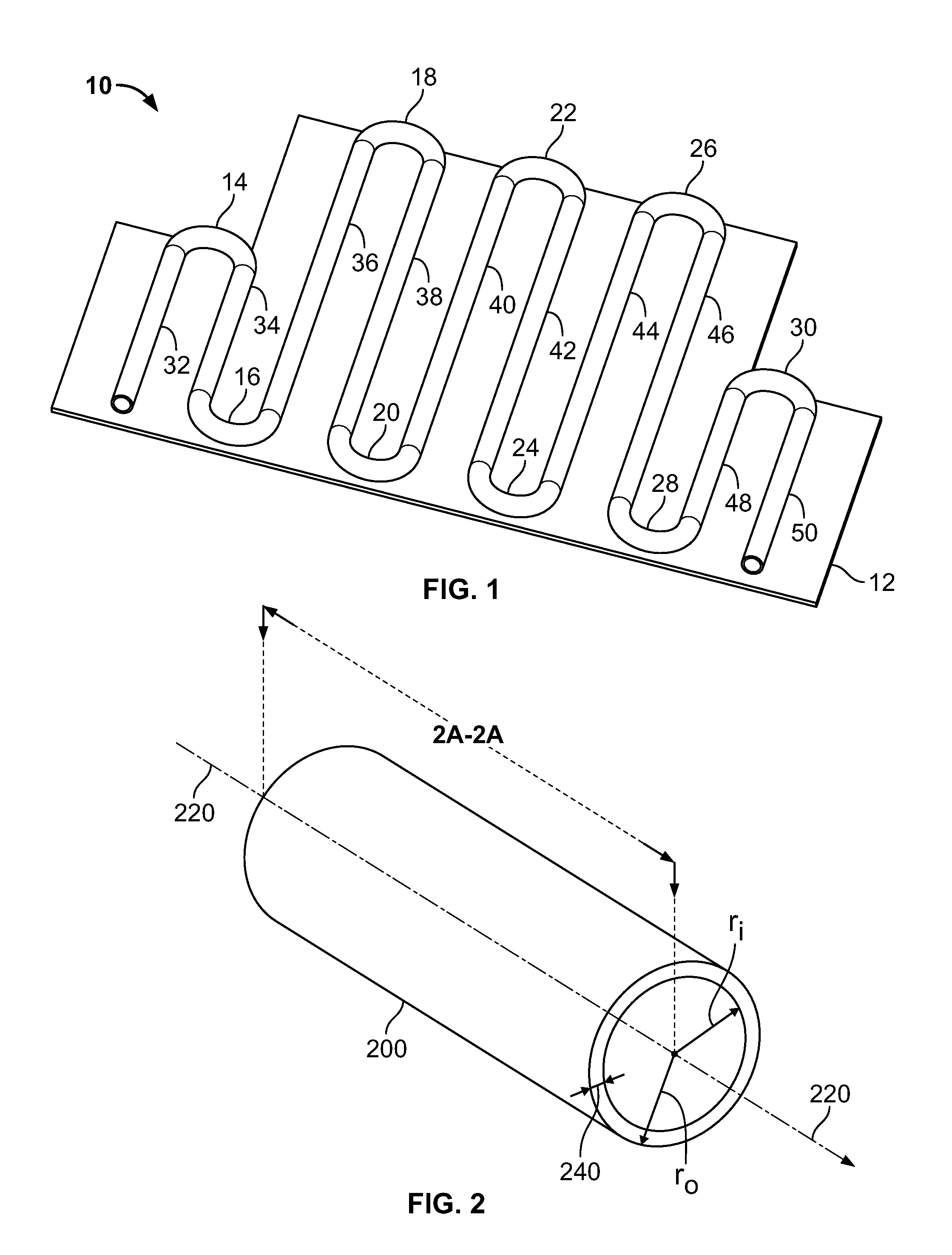
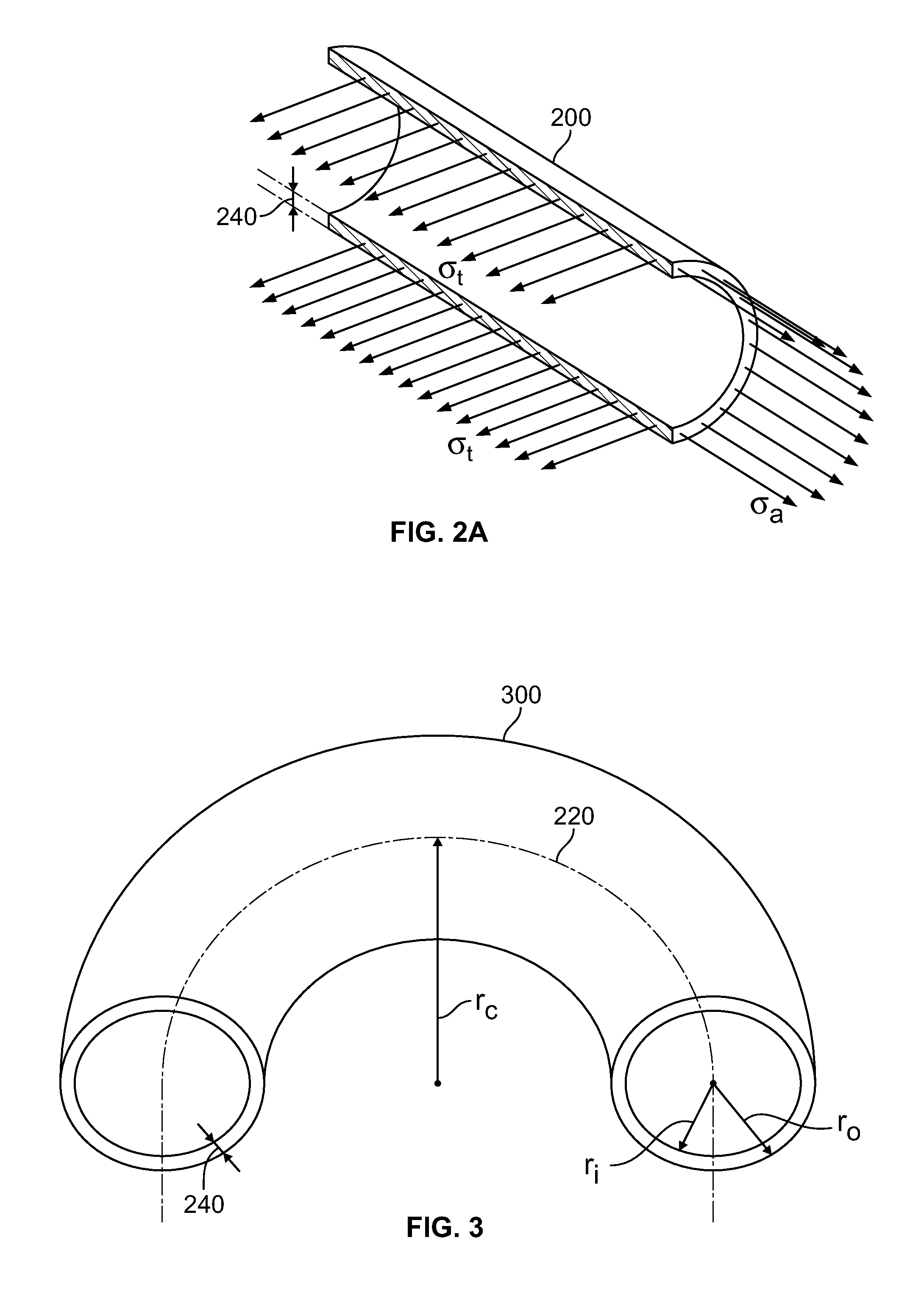
[0041]A particular implementation which can be used for the first and / or second embodiments of the present invention comprises storage elements having two types of shapes, viz., straight cylinders and bent cylinders having equal outer diameters (D0, where 2*r0=D0; r0 is the outer radius) and inner diameters (Di, where 2*ri=Di; ri is the inner radius); all of the bent cylinders have equal curve radii (rc). The curve radius for each of the bent cylinders is equa...


PUM

PropertyMeasurementUnit
angleaaaaaaaaaa
pressureaaaaaaaaaa
Young's modulusaaaaaaaaaa

Abstract

A Hydrogen storage system comprising storage elements coupled to each other to form one or more containers disposed in a space having a volume V where the volume of each of the storage elements is much smaller than the volume V resulting in the storage elements experiencing reduced stress at their inner surfaces. Thus, Hydrogen can be stored at relatively high pressure within these storage elements due to the reduced stress experienced by their inner surfaces. Consequently, materials having relatively lower tensile strength and stiffness can be used to construct the storage elements of the Hydrogen storage system. Further, the storage elements can be shaped and sized to conform to a volume of space having an arbitrary shape and dimensions.

Description

BACKGROUND OF THE INVENTION[0001]1. Field of the Invention[0002]The present invention generally relates to hydrogen storage systems for a defined space and more particularly relates to the architecture, size, shape and positioning of such systems for a defined space in vehicles or in storage areas.[0003]2. Description of the Related Art[0004]Hydrogen is increasingly becoming a fuel used in all types of vehicles including bi-fuel vehicles where the other fuel is gasoline. There is however a key practical consideration associated with the use of Hydrogen as a fuel for vehicles. The key consideration is the storage of the hydrogen fuel itself; this consideration raises several issues. In particular, the size, cost of manufacture, and weight of hydrogen tanks are issues that complicate the design and practicability of such tanks Also, the storage mass of the Hydrogen is itself a key consideration.[0005]A first issue is the size of the tanks relative to the space allocated to them in veh...

Claims


Application Information

Patent Timeline
Patent Type & Authority Applications(United States)
IPC IPC(8): B65D85/00
CPCF17C1/005F17C2270/0581F17C2201/0104F17C2201/0138F17C2201/0147F17C2201/0157F17C2203/0604F17C2203/0621F17C2203/0643F17C2203/0646F17C2203/0648F17C2203/0663F17C2205/0146F17C2205/0352F17C2209/2154F17C2221/012F17C2223/036F17C2260/018F17C2260/036F17C2270/0168F17C2270/0178Y02E60/321Y02E60/32
Inventor WELLNITZ, JORG
Owner ALSET IP SARL
Why Eureka
Try Eureka