Rotary electric machine

Inactive Publication Date: 2013-04-18
MITSUBISHI ELECTRIC CORP
View PDF4 Cites 12 Cited by
  • Summary
  • Abstract
  • Description
  • Claims
  • Application Information

AI Technical Summary

Benefits of technology

[0010]Intended to solve the aforementioned problems of the prior art, the present invention has as an object the provisi

Problems solved by technology

This AC motor therefore has a problem that the motor can not be sufficiently cooled when the temperature thereof has increased under operating conditions, because the stator and the stator retaining ring can not easily dissipate heat.
As a consequence, contact pressure between the iron sleeve and the housing increases by compression, causing a compressive stress in the stator which is disposed in close contact with the inner surface of

Method used


Image

  • Rotary electric machine
  • Rotary electric machine
  • Rotary electric machine

Examples


first embodiment

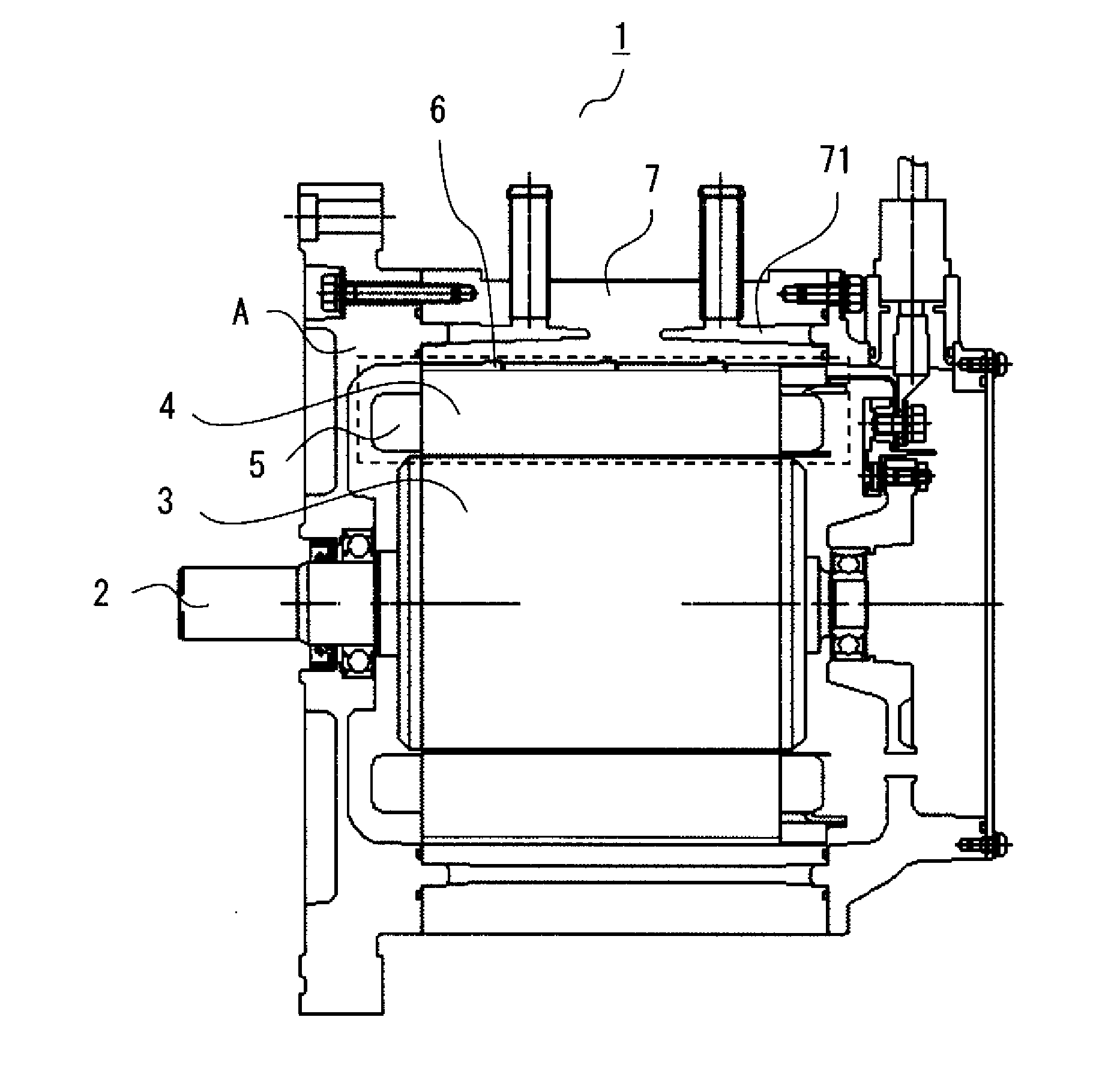
[0028]FIG. 1 is a cross-sectional diagram illustrating the configuration of a rotary electric machine 1 according to a first embodiment of the present invention.

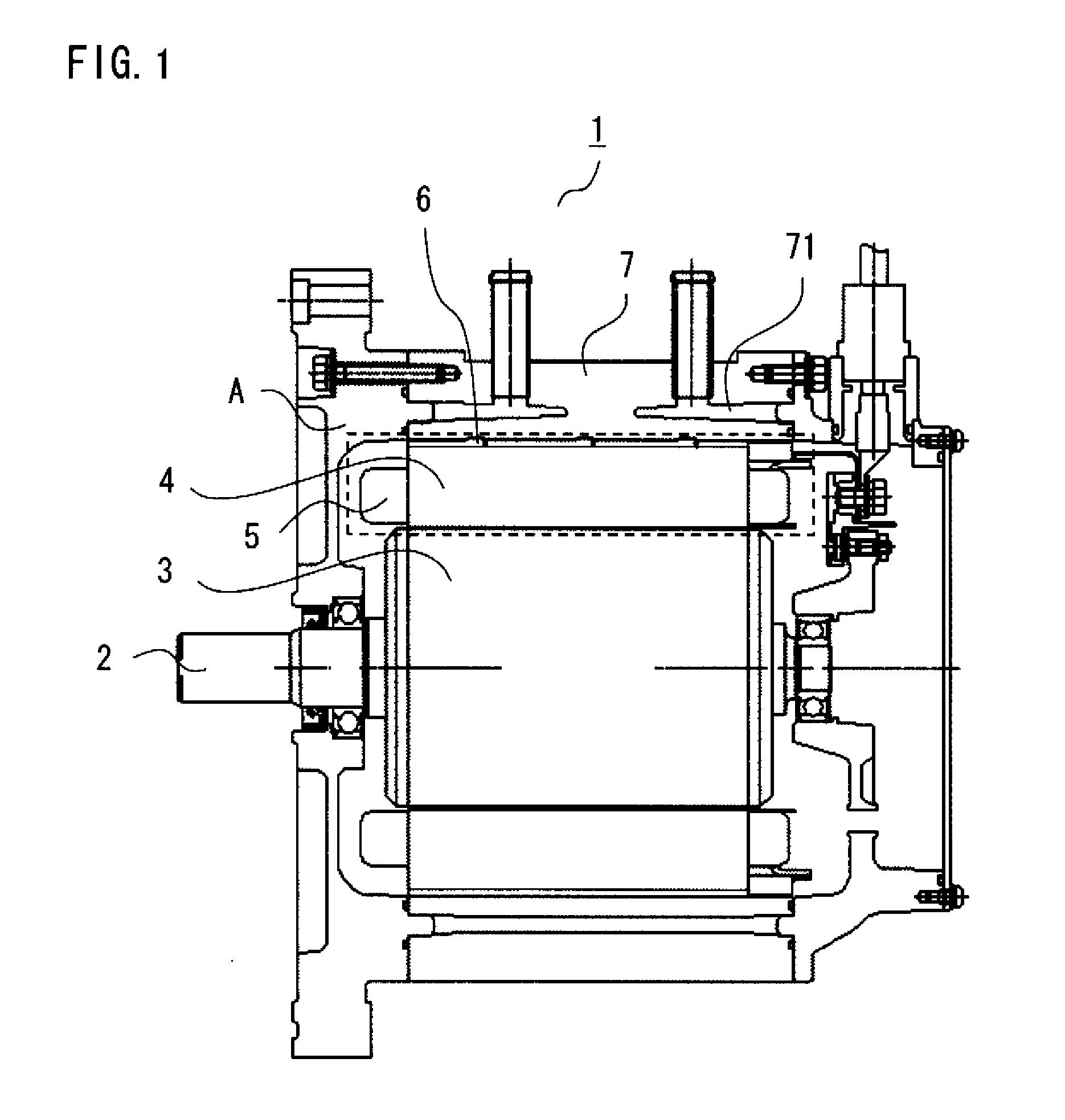
[0029]As depicted in FIG. 1, the rotary electric machine 1 includes a rotor 3 mounted on a rotary shaft 2, a ring-shaped stator 4 arranged to surround an outer surface of the rotor 3. The stator 4 essentially made of iron is a split-type stator including a plurality of stator pieces on which coils 5 are wound, the stator pieces being arranged in a ringlike structure. On the outside of an outer periphery of the split-type stator 4, there is provided a cylindrical, thin-walled ring member 6 made of iron which is the same material as that of the stator 4. The ring member 6 and the stator 4 are fixed on a common axis with the ring member 6 mounted on the stator 4 by shrinkage fitting. On the outside of an outer periphery of the ring member 6, there is disposed a cylinder-shaped aluminum frame 7 having an inside diameter which is...

second embodiment

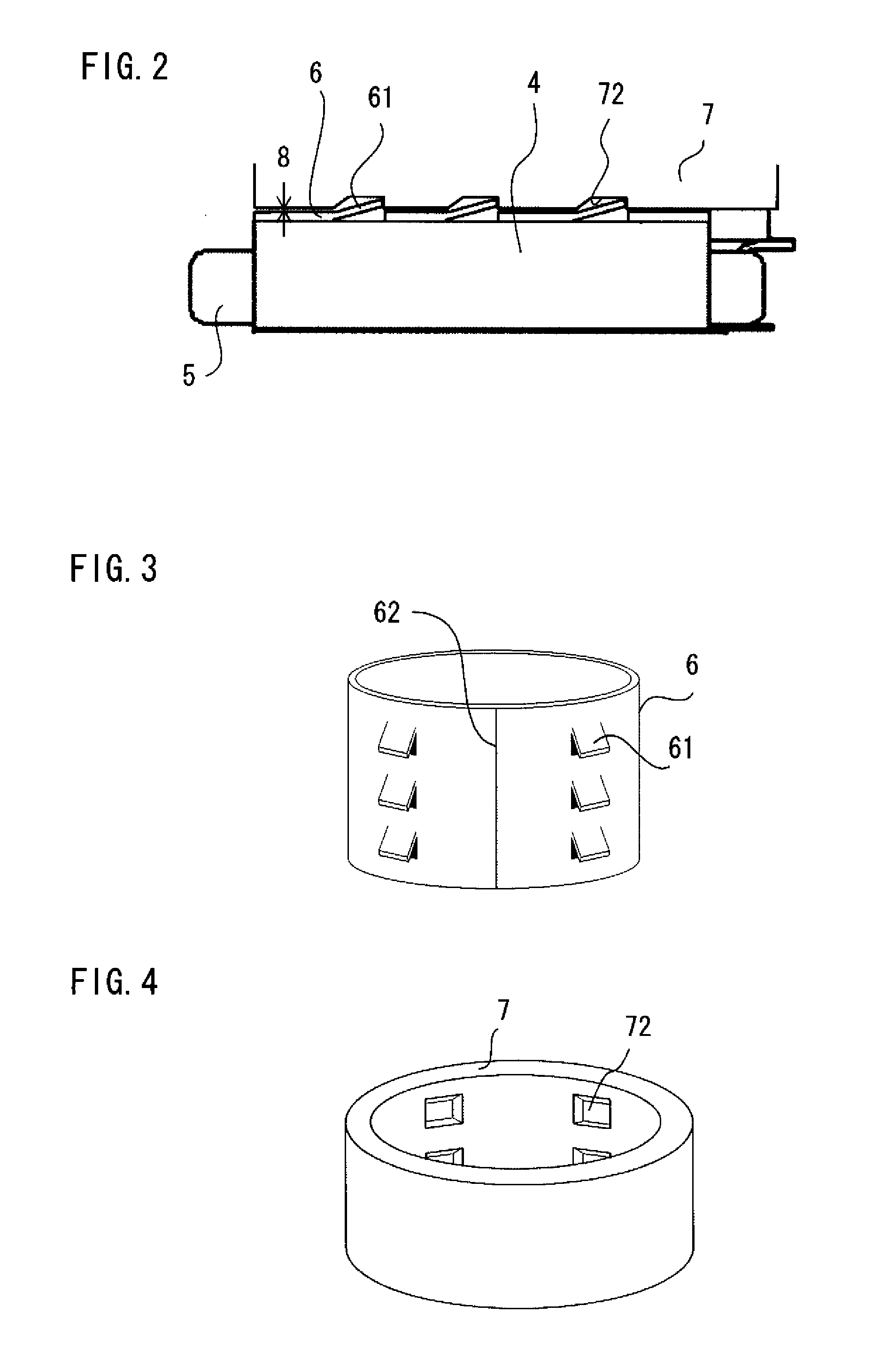
[0060]FIG. 9 is a perspective view depicting the structure of a ring member 6B of a rotary electric machine 1B according to a second embodiment of the present invention. The ring member 6B has a second hooking part 63 which serves as a supporting portion in addition to hooking parts 61 which are structured in the same fashion as those of the above-described first embodiment. The second hooking part 63 of the second embodiment which is located at an uppermost axial end (as illustrated) of the ring member 6B is formed by cutting and bending part of the ring member 6B along a direction deviating from a cut-and-bend direction of the hooking parts 61 by 90 degrees. A frame 7B which supports the ring member 6B is provided with a second recess in which the second hooking part 63 is retained at a location corresponding to the second hooking part 63. The rotary electric machine 1B is structured in otherwise the same fashion as the rotary electric machine 1 of the foregoing first embodiment, ...

third embodiment

[0062]FIG. 10 is a perspective view depicting the structure of a ring member 6C of a rotary electric machine 1C according to a third embodiment of the present invention. The ring member 6C employed in this embodiment is a tolerance ring of which entire ring structure has a springy characteristic. Specifically, the ring member 6C employed in the third embodiment is a tolerance ring having a plurality of protrusions 64 formed on an outer surface of the ring member 6C to extend along an axial direction thereof. A frame 7C employed in the third embodiment has a simple thin-walled cylindrical structure unlike the ring member 6 of the first embodiment in which the recesses 72 are formed. The plurality of protrusions 64 serve as supporting portions for supporting the ring member 6C within the frame 7C. To be more specific, the protrusions 64 serving as the supporting portions are in contact with an inner surface of the frame 7C so that the ring member 6C is supported on the inside of the f...


PUM


Abstract

A rotary electric machine includes a rotor, a stator having coils wound to surround the rotor, a cylindrical ring member fixedly mounted on the stator by shrinkage fitting, and a frame disposed on the outside of the ring member with a gap created in between. The distance of the gap varies as a result of thermal expansion of the stator and the ring member. An outer surface of the ring member goes into contact with the frame when the stator and the ring member thermally expand, whereby the stator and the ring member are efficiently cooled.

Description

BACKGROUND OF THE INVENTION[0001]1. Field of the Invention[0002]The present invention relates to a structure of a rotary electric machine and, more particularly, to a rotary electric machine capable of efficiently cooling a stator thereof and having excellent magnetic properties.[0003]2. Description of the Background Art[0004]A conventional AC motor includes a stator configured with a plurality of independent stator pieces on which stator coils are wound, the stator pieces being arranged in a ringlike structure, and a stator retaining ring having an opening in which the stator is fixed by press-fitting, wherein the stator retaining ring and a motor housing are fixed by screws. This kind of AC motor is described in Japanese Patent Application Publication No. 2001-025187, for example.[0005]An example of a conventional rotary motor includes a cylindrical aluminum housing, a cylindrical iron sleeve fixedly arranged on a cylindrical inner surface of the housing, and a ring-shaped stator ...

Claims


Application Information

Patent Timeline
IPC IPC(8): H02K9/00
CPCH02K1/148H02K2201/03H02K9/22H02K1/185H02K9/227
Inventor MURAKAMI, TADASHIOJIMA, KOUICHIINOUE, MASAYA
Owner MITSUBISHI ELECTRIC CORP
Why Eureka
Try Eureka