Sport performance monitoring apparatus, process, and method of use

a technology of performance monitoring and monitoring apparatus, applied in the field of sports training devices, can solve the problems of racers losing edge control, difficulty in teaching proper form of ski turns, and difficulty in achieving full range of problems, so as to improve the quality and quantity of feedback, improve the accuracy of feedback, and facilitate the effect of determination

Inactive Publication Date: 2013-04-18
BENDER CHRIS NORCROSS
View PDF6 Cites 10 Cited by
  • Summary
  • Abstract
  • Description
  • Claims
  • Application Information

AI Technical Summary

Benefits of technology

[0021]In some embodiments, the bladder can be naturally, conveniently, and / or imperceptibly held in place by friction as a result of the large surface area being in contact with the bladder. In some embodiments, the bladder can allow for a distribution of pressure against and along the surface of the leg within the boot, thus improving comfort and in some instance providing easier long-term use. At least certain embodiments of a bladder can be more economical to implement than one or more piezoelectric or other electronic pressure sensing devices.
[0035]In some embodiments, the system includes sensor transmission techniques that seek to minimize interference between the system's multiple transmitters. In certain instances, the technique includes unconditional asynchronous transmission by the secondary sensor / transmitter and selective or conditional asynchronous transmission by a master sensor / transmitter that monitors the unconditional asynchronous transmission.

Problems solved by technology

Teaching and training proper form with respect to ski turns is particularly difficult due to both the difficulty in externally observing forward or other pressure and ski proximity, as well as the inability to communicate the form break to the skier at the moment the problem occurs.
Shaping of the ski does make skiing easier, but it does not by itself solve the full range of issues that result from improper pressure distribution and ski proximity.
For example, in ski racing, if the skier is not leaning forward sufficiently, a turn can be initiated, but the racer can lose edge control as a result, skidding and losing speed or time through the course as a result.
This loss of control in one turn can cause further loss of control in one or more subsequent turns as well as complete loss of control and exit from the race course.
These systems have proven to be too inaccurate due to their small size and inability to detect leg pressure across the surface of the tongue of the ski boot
Additional disadvantages of the use of electronic spot sensors included the cost of electronic sensors, the use of multiple sensors to obtain accurate monitoring in a single ski boot, frequent adjustment to the location of the sensor within the boot in order to obtain the most accurate monitoring, and compromised durability due to susceptibility to weather conditions and friction.
Yet another disadvantage of these electronic systems is that have not provided any detection of ski proximity.
The applicants have discovered that, since ski proximity is such an important part of proper turn execution as well as in other aspects of skiing, the lack of proximity monitoring results in an incomplete solution to the training challenges surrounding proper ski turns and other aspects of skiing.
Another disadvantage of prior electronic methods is many have not reported changes in pressure against the tongue of a ski boot of each limb independently.
Further, the absence of independent, limb-associated sensors has prevented the skier from being able to adjust sensitivity independently for each sensor.
This has resulted in an underreported window of improper pressure for one of the two limbs.
Prior systems for monitoring skier lean have also typically employed uncomfortable or cumbersome mountings to the ski boot, the ankle, or a combination of the ski boot and ankles.
Many of these systems have required semi-permanent to permanent positioning within the ski boot, making maintenance and location adjustment difficult.

Method used


Image

  • Sport performance monitoring apparatus, process, and method of use
  • Sport performance monitoring apparatus, process, and method of use
  • Sport performance monitoring apparatus, process, and method of use

Examples


Embodiment Construction

[0055]The following description provides examples, and is not limiting of the scope, applicability, or configuration set forth in the claims. Changes may be made in the function and arrangement of elements discussed without departing from the spirit and scope of the disclosure. Various embodiments may omit, substitute, or add various procedures or components as appropriate. For instance, the methods described may be performed in an order different from that described, and various steps may be added, omitted, or combined. Also, features described with respect to certain embodiments may be combined in other embodiments.

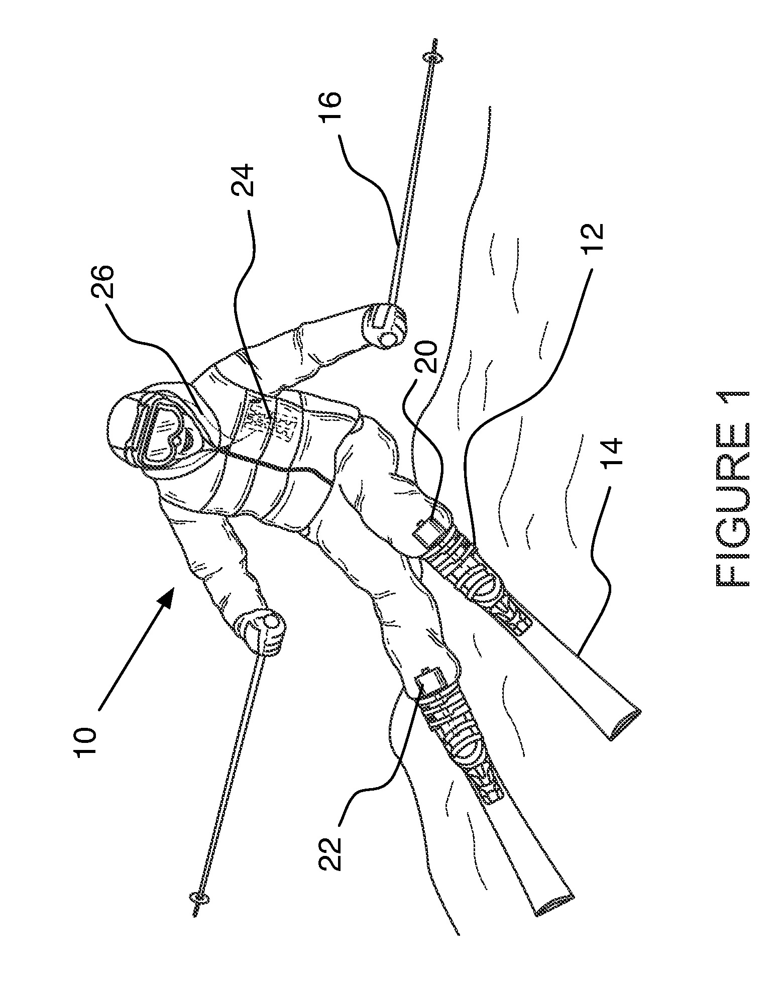
[0056]With reference to FIG. 1, a skier 10 wearing ski boots 12, which are connected to a pair of skis 14, and holding a pair of ski poles 16 is described. The skier 10 is using an exemplary embodiment of a sports monitoring system, which includes two boot sensor units 20, 22 in communication with a hand controller unit 24. The boot sensor units 20, 22 communicates info...


PUM

PropertyMeasurementUnit
exterior radiusaaaaaaaaaa
depthaaaaaaaaaa

Abstract

A sports monitoring system and method. One disclosed system can be used during skiing and includes a controller transceiver that can be hand held, two ski boot pressure monitor / transmitters, and earphones connectable to the controller / transceiver. The system can be used to provide, through the earphones, sound indicative of pressure applied or not applied by a skier toward a portion of a boot while skiing. The system may also include a proximity sensor mounted within one of the ski boot pressure monitor / transmitters. The system can thereby provide sound responsive to the proximity detector's detection of one boot being at or not at a distance, or within or outside of a distance range, with respect to the other boot.

Description

RELATED APPLICATIONS[0001]The present application for patent claims priority to U.S. Provisional Application No. 61 / 547,614 entitled “SPORT PERFORMANCE MONITORING APPARATUS, PROCESS AND METHOD OF USE,” filled Oct. 14, 2011 and U.S. Provisional Application No. 61,713,464 entitled “SPORT PERFORMANCE MONITORING APPARATUS, PROCESS AND METHOD OF USE,” filled Oct. 12, 2012, both of which Provisional Applications are hereby expressly incorporated by reference in their entirety including the source code appendix of U.S. Provisional Application No. 61,713,464.COPYRIGHT NOTICE[0002]A portion of the disclosure of this patent document contains or may contain material subject to copyright protection. The copyright owner has no objection to the photocopy reproduction of the patent document or the patent disclosure in exactly the form it appears in the Patent and Trademark Office patent file or records, but otherwise reserves all copyright rights.FIELD OF INVENTION[0003]The present invention relat...

Claims


Application Information

Patent Timeline
Patent Type & Authority Applications(United States)
IPC IPC(8): G01N3/08G08B1/08G08B21/18
CPCG09B19/0038A43B5/0415A43B3/0021A43B3/0015A43B3/50A43B3/38A63B24/0062A63B69/18G01N3/08G08B3/10
Inventor BENDER, CHRIS NORCROSSBISHOP, ROGER S.VETTER, KAY DANIEL
Owner BENDER CHRIS NORCROSS
Why Eureka
Try Eureka