Acoustic structure of porous material

a porous material and acoustic structure technology, applied in the field of three empirical equations in frequency domain, can solve the problems of inability to accurately provide, inability to accurately predict sound absorption coefficient, and high inaccuracy in modeling porosity, so as to simplify material similarity analysis and save database storage. , the effect of saving the database storag

Inactive Publication Date: 2008-10-09
MAO CHI MIN
View PDF0 Cites 4 Cited by
  • Summary
  • Abstract
  • Description
  • Claims
  • Application Information

AI Technical Summary

Benefits of technology

[0014]The aforementioned long felt needs are met, and problem solved, by having the exact material properties provided in accordance with the present invention. In a preferred embodiment, the empirical functions comprise an acoustic dispersion relationship for estimation and prediction on elastic porous materials properties in a wide frequency range. The empirical functions further consists of three equations to solve for three important material properties: the porosity, specific air mass in pore and flow resistance. Still more preferably, these empirical functions predict acoustic absorption on almost every elastic porous material without loss their accuracy. Still more preferably, using real, one-time measured material data at a specific thickness, materials properties at other thickness are predictable in a wide frequency range.
[0015]In a further preferred aspect of the invention, each robust empirical function is mathematically and physically understood and is a summation of many individual orthogonal functions with adjustable coefficients. These coeffic

Problems solved by technology

These early measurement methods actually measure single sound absorption properties of the material, and did not rely on data and model analysis techniques to complete crucial measurement on frequency-dependent properties of the porous material owing to the limit of the test equipment.
Over the same course of time, the growth of the new materials was fast but the information about these fundamental properties are still limited This results in the increased importance on the research of the material modeling, the acoustic modeling and the time-intensive numerical computation.
For the lack of good understanding of fundamental properties, M, P and R, the error of the prediction of sound absorption coefficient is not negligible and often misleads to select correct material from a wide range of the materials at early design stage.
Up to now, the current technology are still not able to correctly provide, for example, us the detail mechanism of how air flow resistance, a measurement of air permeability of the material, was effected by the frequency in audio range, and how it was coupled by other properties such as the porosity and the added air mass.
Even if the introduction of the sophisticated equipment, the inaccuracy on modeling the porosity is still high due its size of the micro-structure and its irregularity.
The size of the pore is in the range of 10−5 to 10−6 met

Method used


Image

  • Acoustic structure of porous material
  • Acoustic structure of porous material
  • Acoustic structure of porous material

Examples


Embodiment Construction

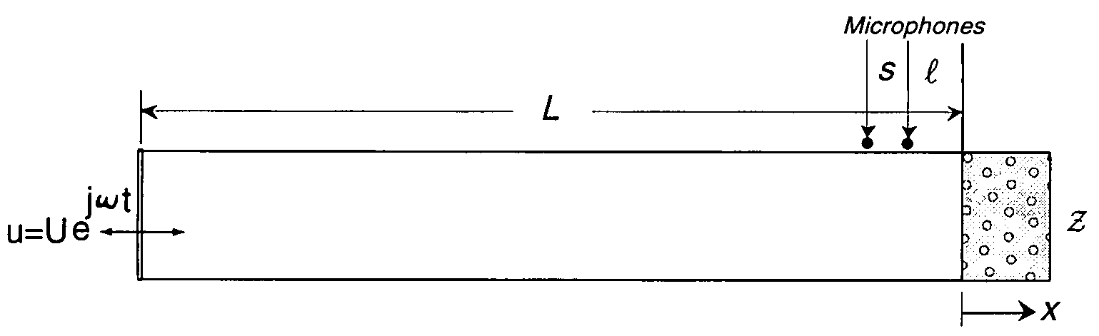
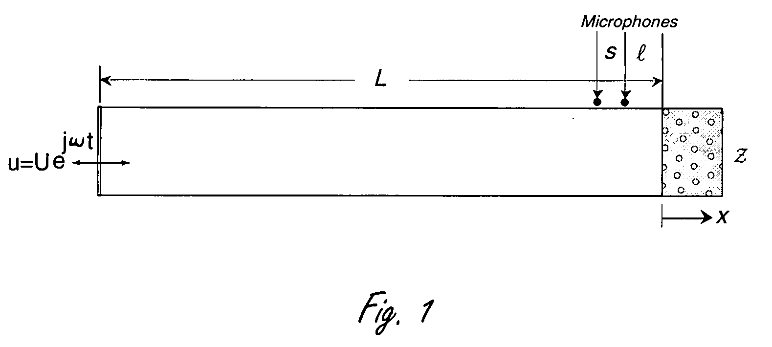
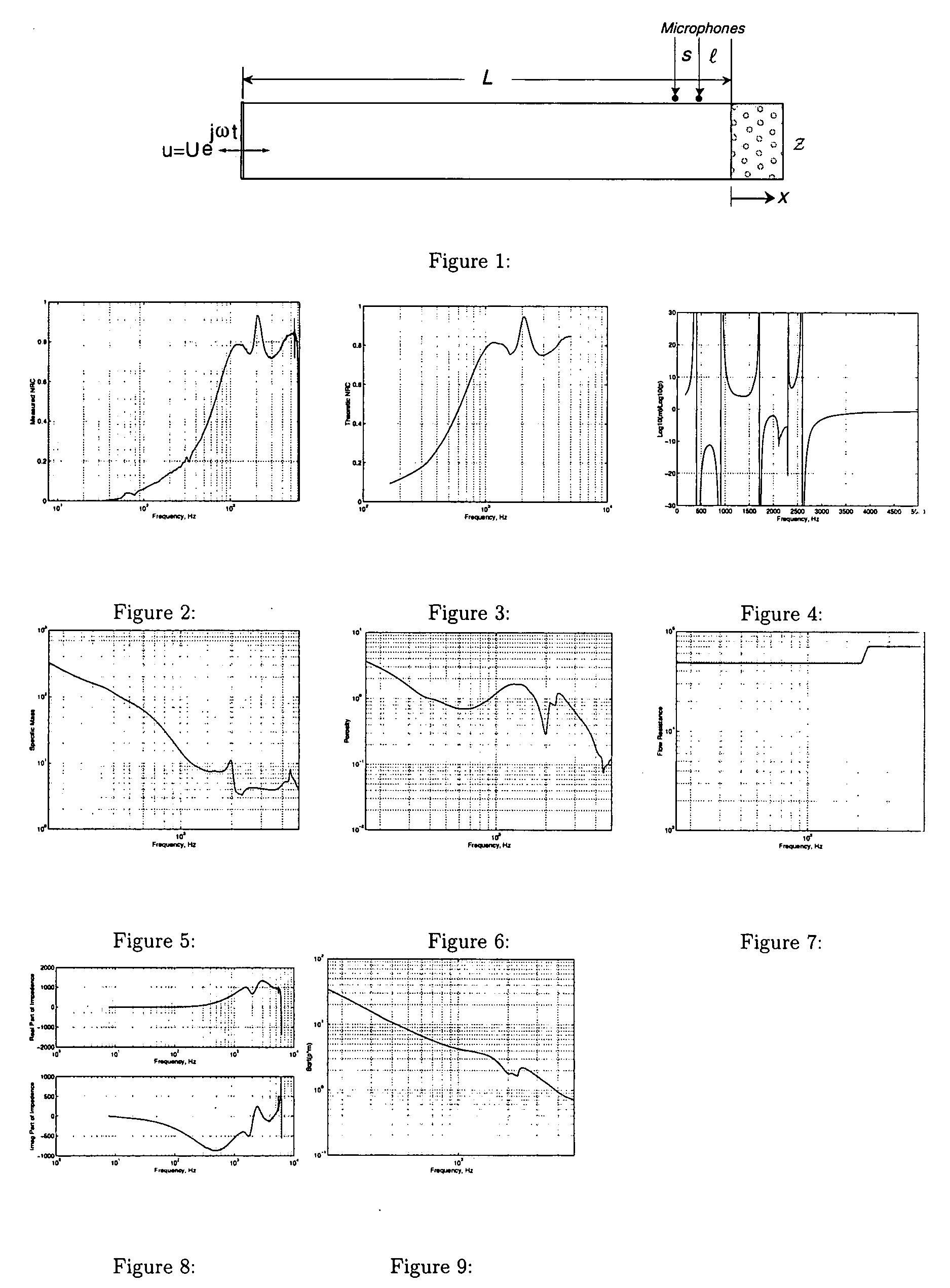
Impedance Tube and Material Structure Modeling

[0018]Let us consider one dimensional acoustic wave equation:

∂2p(x,t)∂t2=c2∂2p(x,t)∂x2(1)

and the boundary conditions

∂p(x,t)∂x|x=-L=-ρ∂u(t)∂t(2)p(x,t)u(t)|x=0=Zb(3)

where c is the speed of sound. ρ is the density of air. u(t) is the external velocity excitation source. Zb is the surface acoustic impedance of the porous material as shown in FIG. 1. p(x, t) is the sound pressure distribution in the tube. The solution of p(x, t) in Eq. 1 can be expressed as

p(x,t)=c1(ωt+kx)+c2(ωt-kx)wherek=ωc(4)

is the wave number of the sound. By using the boundary conditions 2 and 3 and defining

r=c1c2,

we can obtain the surface acoustic impedance

Zb=-ρcr+1r-1(5)

[0019]To solve for two unknowns, Zb and r in Eq. 5, we need one more equation that can be derived by two sound pressure p1=p(−l) and p2=p(−l−s), see FIG. 1, in the form of transfer function.

G12=p1p2,

to solve for p. After manipulation using Eq. 4, we can solve for r as

r=G12--ksks-G122k(+s)(6)

[0020]In prac...


PUM


Abstract

Empirical equations for porous material to describe the frequency property of the microstructure and predict their sound absorption performance. These empirical equations systematically establish a solid system that relates the porosity, the flow resistance and the air mass to their frequency property and describe how to predict sound absorption coefficient in different thickness. These empirical equations reveal that the microstructure are not uniform across the thickness when the materials are exposed to the sound field. The flow resistance is one of the microstructure and is found to be a step function of the frequency. An interchangeability between the thickness and the frequency was established to predict sound absorption coefficient.

Description

BACKGROUND OF THE INVENTION[0001]1. Field of the Invention[0002]This invention relates generally to three empirical equations in frequency domain. More particularly, this invention relates to three empirical equations that compute the porosity of the materials, the added specific air mass in pore and the flow resistance of the flexible porous materials, and which generally predict material properties in different thickness.[0003]2. Description of the Related Art[0004]New Evolution—Same Old Problems—Flexible Porous Material Remains a Matter of Concern in Noise Control[0005]Over the last fifty years, experimental sound and noise control has evolved two concepts: the active noise control using controllable materials (smart materials) such as piezoelectric ceramics (PZT) to cancel unwanted sound or noise and the passive noise control using porous materials or non-porous materials with membrane-like structure to absorb noise, that always induces structure vibration thus result in serious...

Claims


Application Information

Patent Timeline
IPC IPC(8): G06F7/60
CPCG06F17/5009G06F2217/16G06F2111/10G06F30/20
Inventor MAO, CHI-MIN
Owner MAO CHI MIN
Why Eureka
Try Eureka