[0030]The following description of the preferred embodiment(s) is merely exemplary in nature and is in no way intended to limit the invention, its application, or uses.
[0031]Broadly, an embodiment of the present invention provides multiple branch digital predistortion linearization architecture and digital signal processing algorithms for impairments-free operation and linearized multi-band transmitter.
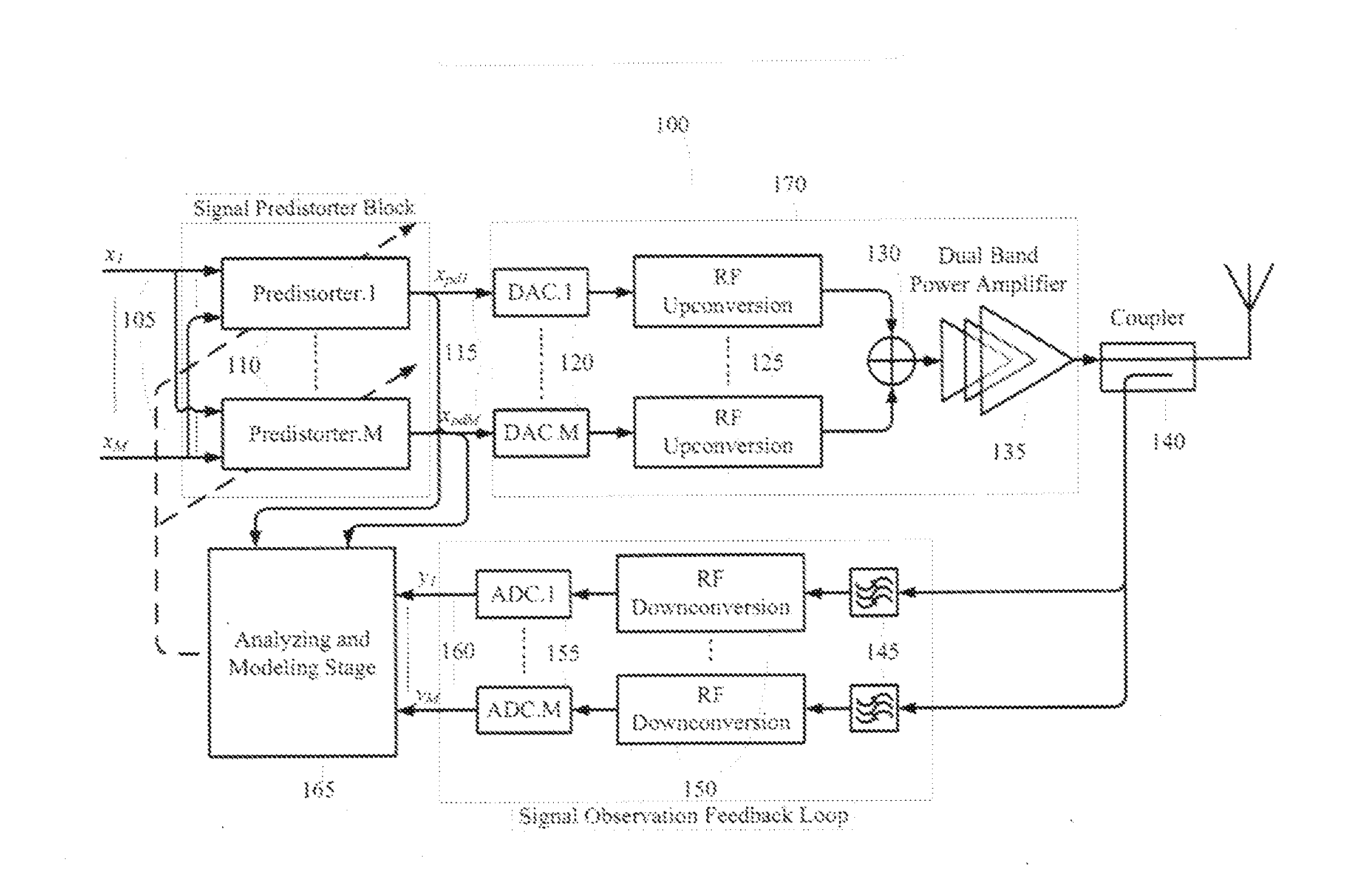
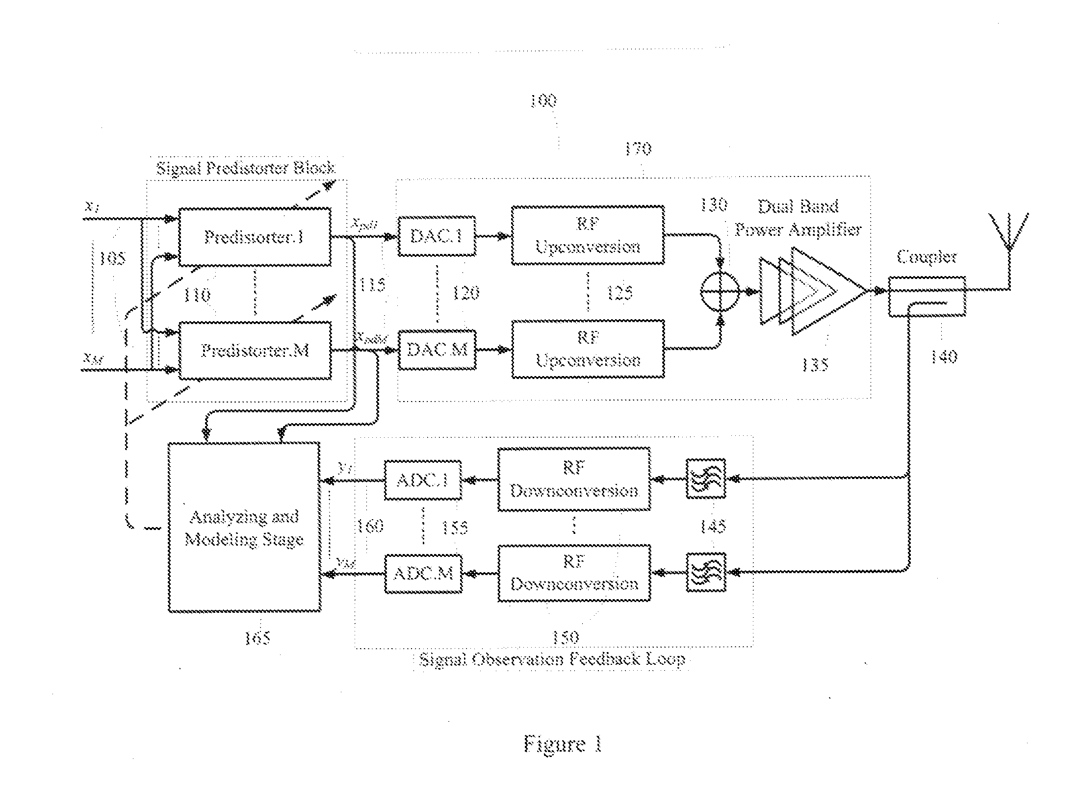
[0032]Referring to FIG. 1, the system block diagram of the dual-band linearization architecture100 is displayed. The input signals, x1 and x2, 105 are fed into two distinct predistorters blocks 110. The predistorted signals 115 are converted from digital to analog 120 and up-converted 125 to RF frequencies. Then the two RF signals are combined 130 and amplified by the power amplifier 135.
[0033]For digital predistortion linearization and identify the inverse model, the sample of the RF signal are captured using dual-band coupler 140. Then the RF signals are bandpass filtered 145, frequency down converted 150, digitized using analog-to-digital converters 155. The digital output samples 160, the input signals 105 and predistorted signals 115 are used in the analyzing stage 165 for nonlinear model identification and reverse modeling.
[0034]The feedback path of the dual-band linearizer requires the use of two down-conversion stages 150, as well as bandpass filters 145 to remove most of the imperfections caused by the power amplifier. The predistorted inputs, xpd1 and xpd2, 115 as well as the output of each band of the PA, y1 and y2, 160 are used to generate the predistorter signal processing model 110. The processing model equations of the linearization processing algorithm 165 for prediction and compensation of the distortions and intermodulations is as follows:
x pd 1 ( n ) = ∑ m = 0 M - 1 ∑ k = 0 K - 1 ∑ j = 0 k c 1 , j , k , m x 1 ( n - m ) x 1 ( n - m ) k - j x 2 ( n - m ) j x pd 2 ( n ) = ∑ m = 0 M - 1 ∑ k = 0 K - 1 ∑ j = 0 k c 2 , j , k , m x 2 ( n - m ) x 2 ( n - m ) k - j x 1 ( n - m ) j ( 1 )
[0035]Where x1(n) and x2(n) are the input signals, xpd1(n) and xpd2(n) are the predistorted signals to the input of the dual-band transmitter, c1,j,k,m and c2,j,k,m are the indentified model's coefficients, and finally M is the order of the memory effect and K is the order of nonlinearity.
[0036]Concurrent multi-band receiver architectures require a bandpass filter 145, down-conversion stage 150, and ADC 155 for the translation of each RF frequency bands to baseband. Using subsampling with a high speed ADC allows the elimination of all these components; however, the user needs to make sure that the signals don't overlap in the subsampled spectral domain.
[0037]Sampling multi-bands at the same time also eliminates the time delay taken between different band paths caused by the filters. FIG. 2 displays the dual-band predistortion architecture with a subsampling feedback loop 200. At the feedback loop, it consists of optional bandpass filters 245, a track and hold 250, an analog-to-digital converter 255, a digital conversion unit 260, and analyzing stage 270.
[0038]Sampling the band-limited RF signal at frequency rates much lower than the carrier frequency, but higher than signal bandwidth folds the RF signal to the lower frequencies, where these replicates of the RF signal at baseband or intermediate frequencies can be used to reconstruct the baseband signal. To make sure that there is no aliasing between the replicas, the subsampling rate should be chosen in the following range:
2 f U n ≤ f s ≤ 2 f L n - 1 where 1 ≤ n ≤ ⌊ f U B ⌋ ( 2 )
[0039]where fL and fU are the lower and upper frequencies of the band-limited RF signal, B=fU−fL is the signal bandwidth, and n is an integer value.
[0040]FIG. 3 shows a general block diagram of subsampling-based receiver 300. It consists of RF bandpass filter 305, low-noise amplifier (LNA) 310, subsampling receiver 345 including the track and hold (T&H) 320, and ADC 325 followed by baseband digital signal processing (DSP) unit 330. The T&H 320 is required to expand the analog bandwidth of the receiver and defines the RF range of receiver operation. The sampling clock of the T&H 320 and ADC 325 are chosen from (2) to avoid any aliasing with the other RF signals.
[0041]In dual-band operation transmitter with nonlinearity, the first and second bands will produce intermodulation, cross modulation and harmonic products. FIG. 4 shows the power spectrum of the input signal, and the output signal when passed through a third order nonlinear system. The input signals as two-tone signal around carrier frequencies of ω1 and ω2 (FIG. 4(a)) the output signals are around carrier frequencies of ω1 and ω2 and the 3rd order intermodulation frequencies of 2ω1−ω1 and 2ω2−ω1 (FIG. 4(b)). The unwanted intermodulation can be classified into three groups of cross-modulation, in-band intermodulation, and out-of-band intermodulation terms. This latter is usually filtered out before transmission using RF filter to avoid signal quality degradation and interference with the signals at the adjacent channels.
[0042]Now considering two RF signals at carrier frequencies of ω2 and ω2, with their respective bandwidths B1 and B2 as shown in FIG. 5, the subsampling frequency, fs, must be chosen to ensure that the two signals do not overlap in the subsampled domain. Taking into account the subsampling theorem for sampling the multi-band signals and following the neighbor and boundary constraints, an iterative process is used to find all the valid subsampling frequencies for the two fundamental frequencies.
[0043]The, out-of-band intermodulation-modulation, and harmonics generated by the fundamental signals are not required for the predistortion application; therefore, an iterative subsampling algorithm has been developed to subsample the RF signals without any overlap with the other unwanted RF signals. FIG. 6 is the flowchart of the developed iterative subsampling algorithm to find the valid subsampling frequencies so that the replicas of the wanted RF signals have no overlap with the harmonics and intermodulation frequency terms.
[0044]Referring to FIG. 7, there is shown the measured output spectrum of the dual-band transmitter 170 for three cases: 1) without using the dual-band digital pre-compensator 110, 2) using the dual-band digital pre-compensator 110 3) the input signal. The output spectrum of case-2 with digital pre-compensator shows that the digital pre-compensator 110 can compensate for the cross-modulation and in-band inter-modulation terms introduced by the transmitter nonlinearity.
[0045]Referring to FIG. 8, there is an example of the power spectrum at the output of the concurrent dual-band nonlinear transmitter which contains two fundamental RF frequencies and their corresponding harmonics and inter-modulation products.
[0046]As an example for the application of this invention, FIG. 9, points up the power spectrum after the subsampling feedback loop which shows the two fundamental RF signals at 260.2 MHz and 118.6 MHz when the subsampling frequency of 619.8 is used following is determination by the developed iterative subsampling algorithm illustrated in FIG. 6. The spectrum in FIG. 9 shows that the harmonics and inter-modulation terms have no interference with the two desired fundamental signals.
[0047]Referring to FIG. 10, there is shown the measured output spectrum of the dual-band transmitter 280 for three cases: 1) without using the dual-band digital pre-compensator 210, 2) using the dual-band digital pre-compensator 210, 3) the input signal. The output spectrum of case-2 with digital pre-compensator shows that the digital pre-compensator 210 can compensate for the cross-modulation and in-band inter-modulation terms introduced by the transmitter dynamic nonlinearity with memory effects.