Acoustic Generator

a generator and acoustic technology, applied in the direction of diaphragm damping, magnetostrictive transducers, mechanical vibration separation, etc., can solve the problem of difficult to achieve satisfactory sound pressure up to ultrahigh frequencies, and achieve the effect of raising the sound pressure and reducing the occurrence of large peak dips

Active Publication Date: 2013-04-18
KYOCERA CORP
View PDF5 Cites 27 Cited by
  • Summary
  • Abstract
  • Description
  • Claims
  • Application Information

AI Technical Summary

Benefits of technology

[0012]In the acoustic generator according to the invention, it is possible to raise the sound pr

Problems solved by technology

However, since an acoustic generator using a piezoelectric element generally uses a resonance phenomenon, it is known that large peak dips occu

Method used


Image

  • Acoustic Generator
  • Acoustic Generator
  • Acoustic Generator

Examples


example 1

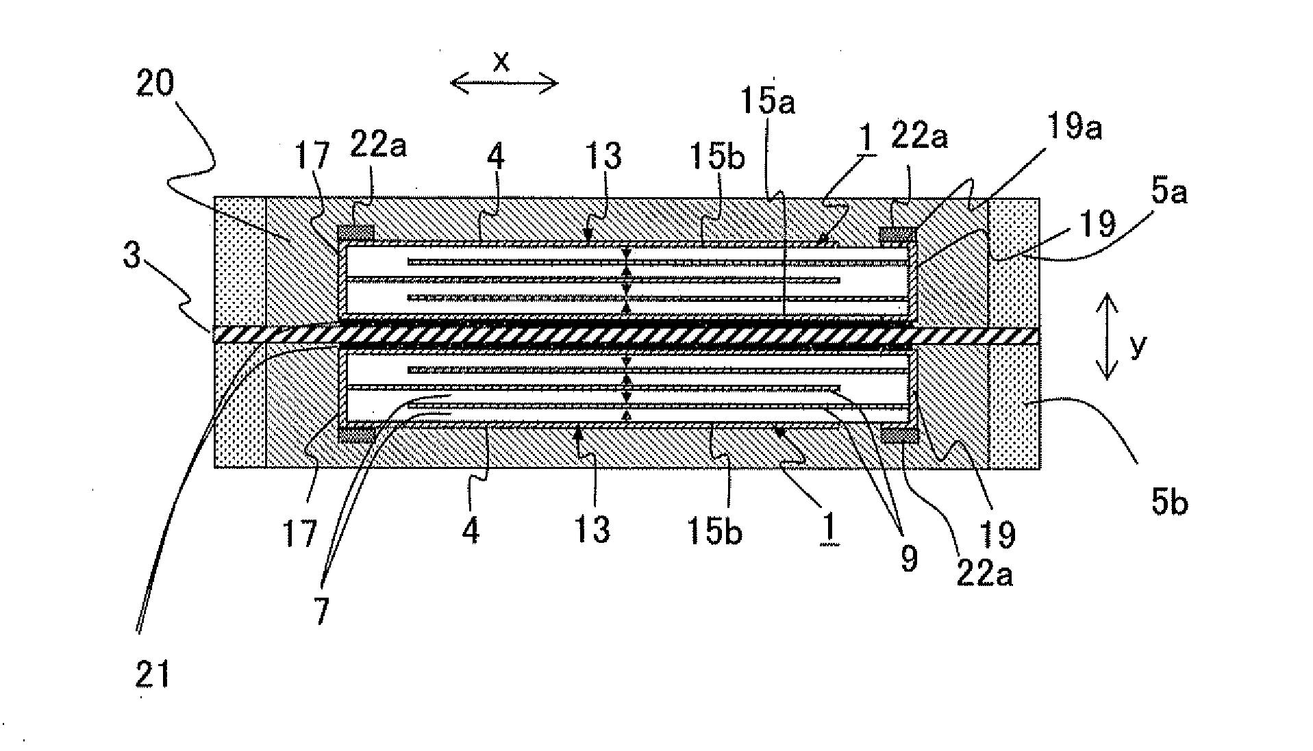
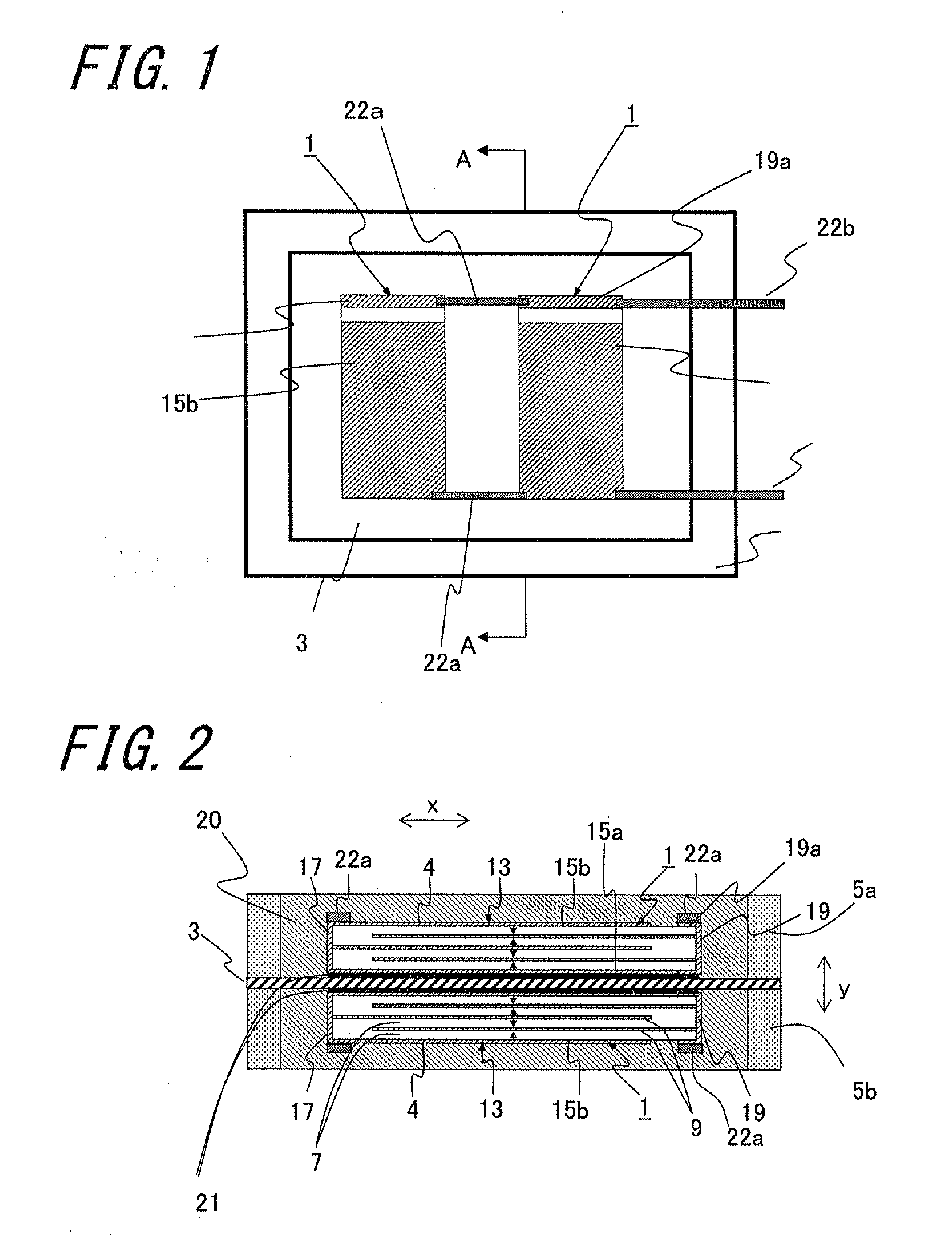
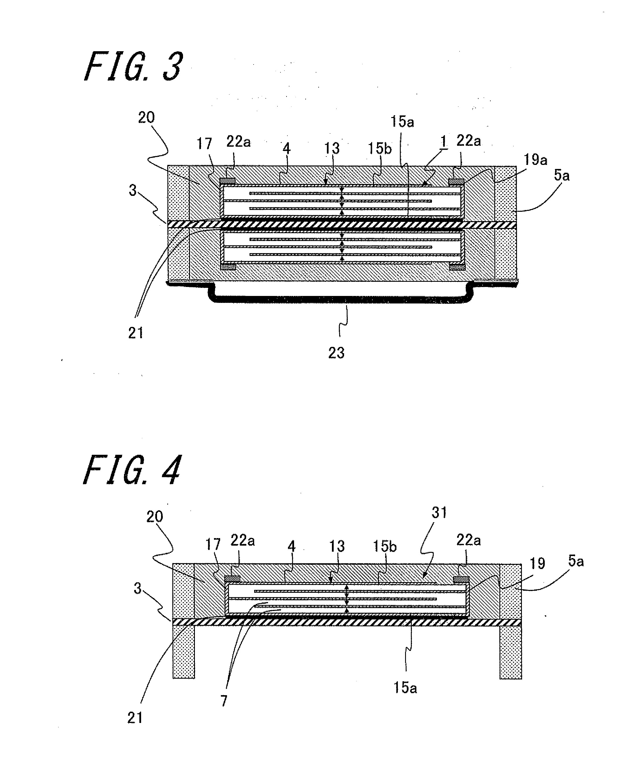
[0088]Piezoelectric powder including lead zirconate titanate (PZT) in which a part of Zr is replaced with Sb, a binder, a dispersant, a plasticizer, and a solvent were kneaded through ball mill mixture for 24 hours to prepare slurry.

[0089]A green sheet was prepared using the resultant slurry through the use of a doctor blade method. Electrode paste including Ag and Pd as an electrode material was applied to the green sheet in a predetermined shape through the use of screen printing, three green sheets having the electrode paste applied thereto were stacked, a green sheet not having the electrode paste applied thereto was stacked as the outermost layer thereof, and the resultant was pressurized to prepare a laminated molded body. The laminated molded body was degreased in the atmosphere at 500° C. for 1 hour, and then was fired in the atmosphere at 1100° C. for 3 hours, whereby a stacked body was obtained.

[0090]Then, both end portions in the length direction x of the obtained stacked...

example 2

[0098]Similarly to Example 1, as shown in FIG. 7, an acoustic generator having four multilayer piezoelectric elements on each of both surfaces of a film was manufactured using unimorph type multilayer piezoelectric elements and sound pressure and frequency characteristics were measured. The results are shown in FIG. 12.

[0099]It could be seen from FIG. 12 that a high sound pressure of about 78 dB and a sound pressure with a small peak dip up to 20 to 150 KHz are obtained and that the peak dip in an ultrahigh frequency band broader than that in Example 1 can be reduced.


PUM


Abstract

Provided is an acoustic generator which has a high sound pressure at ultrahigh frequencies and which can suppress occurrence of large peak dips. An acoustic generator includes a film, a frame member disposed on an outer peripheral edge of the film, a piezoelectric element disposed on the film and inside the frame member, and a resin layer filled inside the frame member so as to cover the piezoelectric element.

Description

TECHNICAL FIELD[0001]The present invention relates to an acoustic generator, and more particularly, to an acoustic generator using a multilayer piezoelectric element.BACKGROUND ART[0002]Recently, to cope with high-quality and ultrabroadband sources such as DVD audio or super audio CDs, speakers capable of reproducing the sound up to ultrahigh frequencies of more than or equal to 100 KHz have been requested. There is also a need for high-pitched speakers capable of reproducing the sound up to ultrahigh frequencies at low cost, without regard to being a single components or small-sized stereo.[0003]Conventionally, a high-pitched speaker in which a vibration diaphragm is driven using a piezoelectric element is suggested. However, since an acoustic generator using a piezoelectric element generally uses a resonance phenomenon, it is known that large peak dips occurred in frequency characteristics of the sound pressure and it is difficult to achieve satisfactory sound pressures up to ultr...

Claims


Application Information

Patent Timeline
IPC IPC(8): H04R17/00
CPCH04R7/26H04R17/00H04R2217/03B06B1/0614B06B1/064B06B1/0603H04R1/26H04R7/02
Inventor FUKUOKA, SHUICHIKUSHIMA, NORIYUKIKAWAMURE, HIROYUKININOMIYA, HIROSHI
Owner KYOCERA CORP
Why Eureka
Try Eureka