Cutting insert and indexable cutting tool

a cutting tool and insert technology, applied in shaping cutters, manufacturing tools, transportation and packaging, etc., can solve the problems of increasing the stock of cutting inserts, increasing tool costs, and requiring replacement of both inserts, so as to suppress the occurrence of burrs or workpiece edge chipping without degrading the cutting condition, and ensuring the cutting condition. , the effect of preventing burrs and workpiece edge chipping

Inactive Publication Date: 2013-04-18
TUNGALOY CORP
View PDF32 Cites 16 Cited by
  • Summary
  • Abstract
  • Description
  • Claims
  • Application Information

AI Technical Summary

Benefits of technology

[0026]When the cutting insert of the present invention is attached to the indexable cutting tool so as to perform a cutting work of a workpiece, the first main cutting edge and the cutting corner portion are in charge of rough cutting processing of the workpiece. In contrast, a part of the ascending inclination portion of the second main cutting edge works as a burr-suppressing edge having a slight cutting edge angle. As a result, even if a burr occurs on a worked surface in the rough cutting processing using the first main cutting edge, the burr is removed by the burr-suppressing edge, and thus the occurrence of burrs or workpiece edge chipping can be prevented. That is, if the cutting insert of the present invention is used, the rough processing and the deburring processing are performed at the same time with one type of the cutting insert. Therefore, processing without burrs under the cutting condition for rough processing is made possible. In other words, the cutting insert of the present invention is capable of suppressing the occurrence of burrs or workpiece edge chipping without degrading the cutting condition.
[0027]A non-cutting recess portion not in contact with the workpiece is formed in the vicinity of the intersection portion between the descending inclination portion and the ascending inclination portion of the second main cutting edge. Since the burr-suppressing edge formed of a part of the ascending inclination portion and the first main cutting edge

Problems solved by technology

The first problem is that, since two types of tips which are the insert for rough processing and the insert for burr suppression are required to be prepared, the types of stocks of cutting inserts increase.
The second problem is that tool lives of the insert for

Method used


Image

  • Cutting insert and indexable cutting tool
  • Cutting insert and indexable cutting tool
  • Cutting insert and indexable cutting tool

Examples


first embodiment

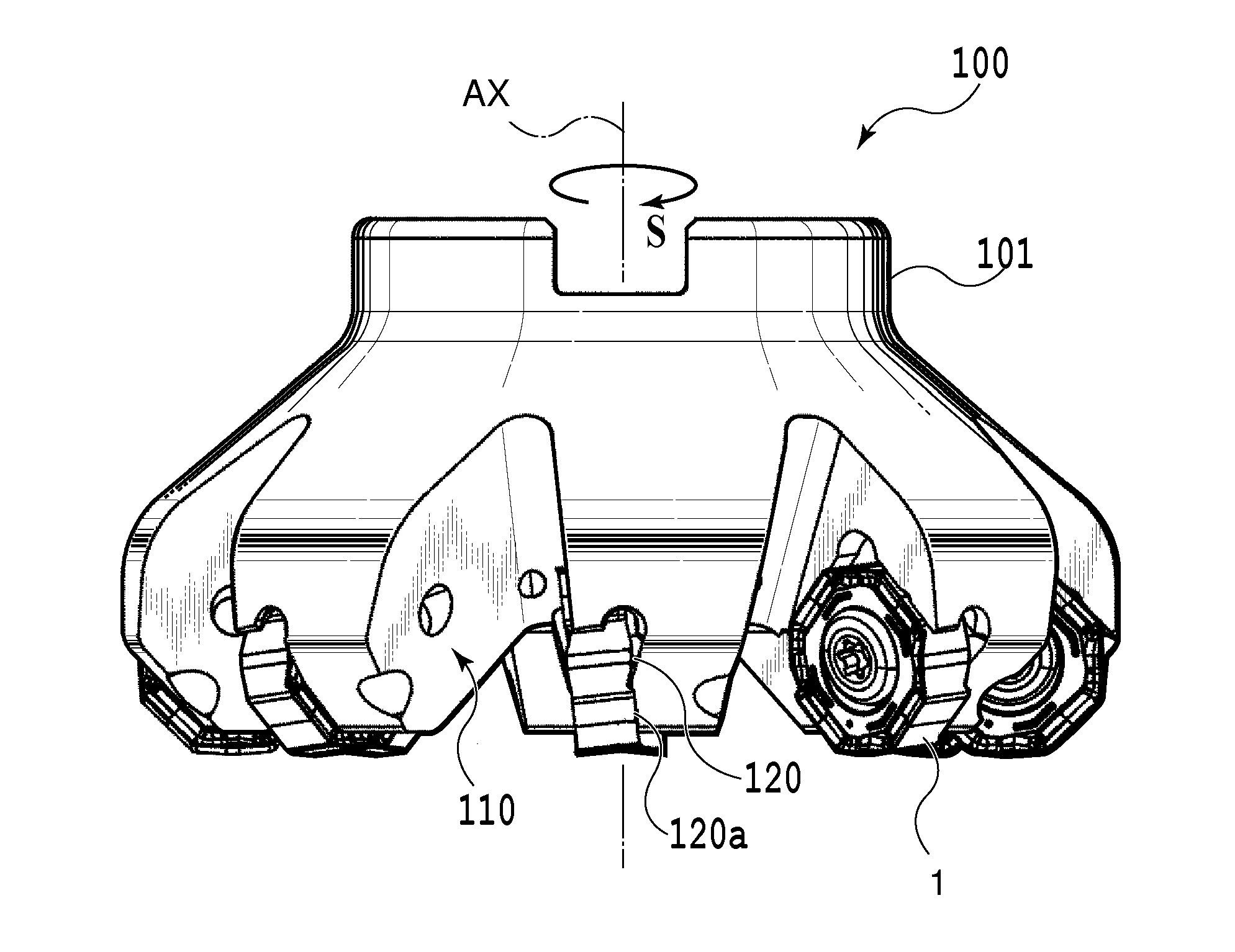
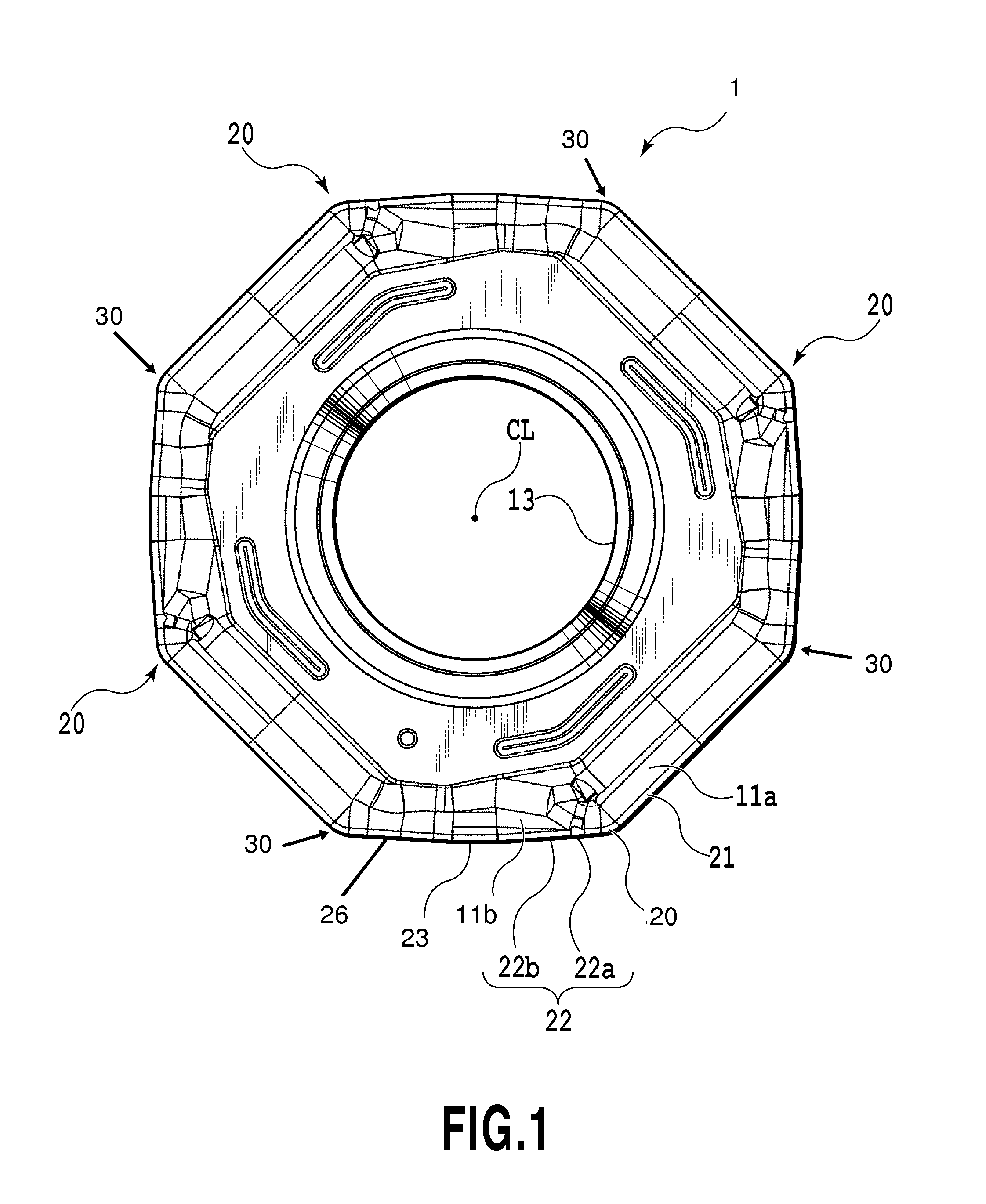
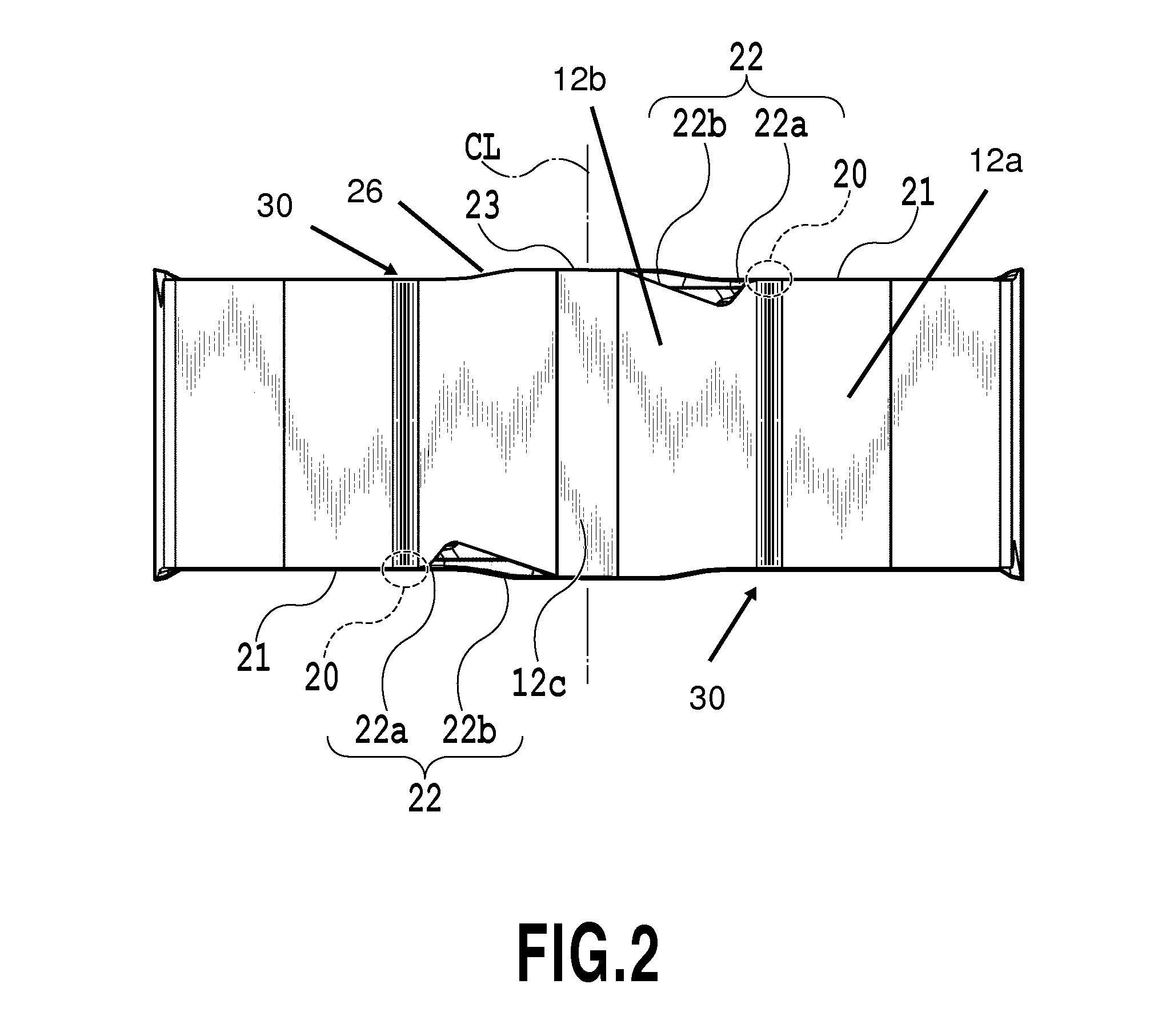
[0048]A cutting insert 1 according to a first embodiment as illustrated in FIGS. 1 to 3 has an approximately octagonal plate shape. A cutting insert 1 has a mounting hole 13 penetrating top and bottom surfaces having a central axis CL at the center. A rake face 11 (11A, 11B) is formed on the approximately octagonal top and bottom surfaces facing away from each other in the central axis CL direction (thickness direction) of the cutting insert 1. A flank 12 (12A, 12B, 12C) is formed on an outer peripheral surface which extends in a direction parallel to the thickness direction between the octagonal surfaces. The cutting insert 1 is indexable about the central axis CL which passes in the middle of the top and bottom surfaces. The cutting insert is also reversible (which is sometimes referred to as “double-sided”) and so is rotationally symmetric by 180° with respect to a transverse axis which is perpendicular to the central axis, parallel to a first main cutting edge and located midway...

second embodiment

[0073]Subsequently, a cutting insert 2 according to a second embodiment will be described by referring to FIGS. 9 to 12. In the configurations of the second embodiment, the same reference numerals as those in the first embodiment are given to the same configurations as those in the first embodiment, and the explanation will be omitted.

[0074]As illustrated in FIGS. 9 to 11, the cutting insert 2 according to the second embodiment has an approximately octagonal plate shape with four cutting corner portions 20 alternating with four non-cutting corners 30. The rake face 11 is formed only on a somewhat irregular octagonal surface on the top surface. The bottom surface of the cutting insert 2 is smaller than the top surface, and the outer peripheral surface extending between the both is inclined toward the inside of the cutting insert 2 as it goes from the top surface to the bottom surface. That is, the cutting insert 2 according to this embodiment is a positive-type insert.

[0075]The flank...


PUM

PropertyMeasurementUnit
Lengthaaaaaaaaaa
Lengthaaaaaaaaaa
Angleaaaaaaaaaa

Abstract

A cutting insert helps prevent the occurrence of burrs and enables highly efficient processing. The cutting edge of the insert includes a cutting corner portion, a first main cutting edge and a second main cutting edge. The second main cutting edge includes a descending inclination portion inclined toward the side of a surface facing the rake face as it separates from the cutting corner portion and an ascending inclination portion inclined toward the side of the surface on which the rake face is formed, as it separates from the cutting corner portion. The descending inclination portion is connected to the cutting corner portion, the ascending inclination portion is connected to the descending inclination portion, and at least a connection region between the ascending inclination portion and the descending inclination portion has a concave curved non-cutting recess portion.

Description

CROSS-REFERENCE TO RELATED APPLICATIONS[0001]This is a Continuation-in-part of International Patent Application No. PCT / JP2011 / 060542, filed May 2, 2011 and published as WO 2011 / 138950A1 on Nov. 10, 2011, which claims the benefit of Japanese Patent Application No. 2010-106794, filed May 6, 2010. The aforementioned applications are incorporated by reference herein in their entirety.BACKGROUND OF THE INVENTION[0002]1. Field of the Invention[0003]The present invention relates to a cutting insert and an indexable cutting tool to which the cutting insert can be attached.[0004]2. Description of the Related Art[0005]Burrs occurring in face milling operation are removed in a deburring process provided after the face milling operation is finished in general. In contrast, regarding workpiece edge chipping occurring in milling operation of a casting, a cutting condition under which workpiece edge chipping rarely occurs is required to be set in general in order to prevent the occurrence. Moreov...

Claims


Application Information

Patent Timeline
IPC IPC(8): B23C5/20B23C5/06
CPCB23C5/06B23C5/207B23C2200/0422B23C2200/201Y10T407/1924B23C5/205Y10T407/235Y10T407/2268B23C2200/205B23C5/202B23C5/20
Inventor YOSHIDA, SATORU
Owner TUNGALOY CORP
Why Eureka
Try Eureka