
Modular drain pan assembly, with seamless floor, for horizontally positioned dual-pass cooling coils

a dual-pass cooling coil and drain pan technology, applied in the field of drain pans, can solve the problems of requiring seams, affecting the service life a potential source of microbial contamination of the drain pan, so as to facilitate the overall length of the drain pan can be increased, and the effect of facilitating the initial assembly or service change-ou

Inactive Publication Date: 2013-04-25
STARK WALTER
View PDF11 Cites 0 Cited by
  • Summary
  • Abstract
  • Description
  • Claims
  • Application Information

AI Technical Summary

Benefits of technology

The invention aims to improve the drainage of water from underground cooling coils. The technical effect of the invention is the efficient removal of water from the cooling system, which helps to prolong the life of the system and prevent damage to the equipment.

Problems solved by technology

Problems with single large drain pans under horizontally extended cooling coils are that they exceed the width of traditional construction materials and therefore require seams in the drain pan floor to join pieces together.
This joining results in potential for leaks, added assembly labor, uneven and non-uniform pan surfaces which thereby increases the required slope to ensure full drainage with no areas of stagnant water.a. Seams in the pan floor increase the possibility of leaks, increase cost of manufacturing and, in the case of stainless steel; heat from welding changes the properties of the metal at the weld joint, causing rust and accelerated deterioration.
Welding long seams of a drain pan material is known to cause “buckling” which leads to pockets of trapped stagnant condensate.
Without proper slope, areas of stagnant water form on the surface of large pans.
These areas of stagnant water are caused by a non-uniform surface that is a natural tendency over large surfaces.

Method used


Image

  • Modular drain pan assembly, with seamless floor, for horizontally positioned dual-pass cooling coils
  • Modular drain pan assembly, with seamless floor, for horizontally positioned dual-pass cooling coils
  • Modular drain pan assembly, with seamless floor, for horizontally positioned dual-pass cooling coils

Examples


Embodiment Construction

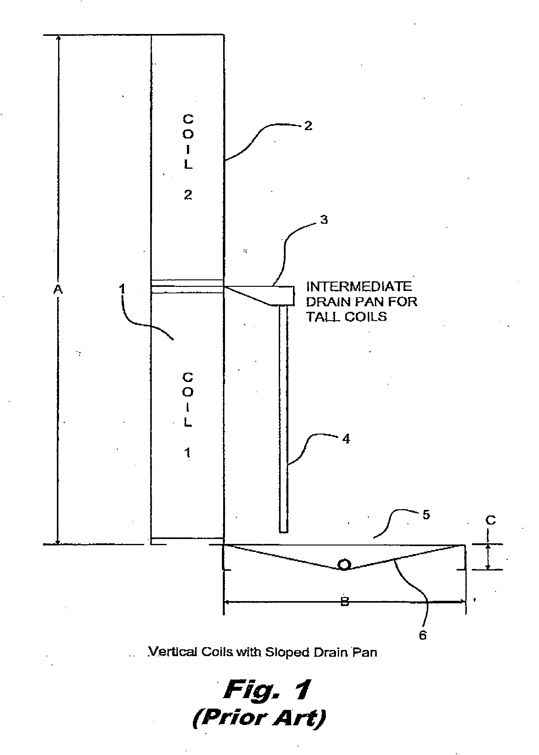
[0037]FIG. 1 shows a prior art tall vertical cooling coil partitioned into a bottom coil 1 with a coil 2 atop. For very tall coils such as this, an intermediate drain pan 3 can be used with a conduit 4 to a main drain pan 5 at the bottom. Note that although the height “A” may be great, the drip surface is modest for this vertically oriented situation and can be serviced by drain pan 5 of modest dimensions (width “B” and height “C”) and sloping bottom 6.

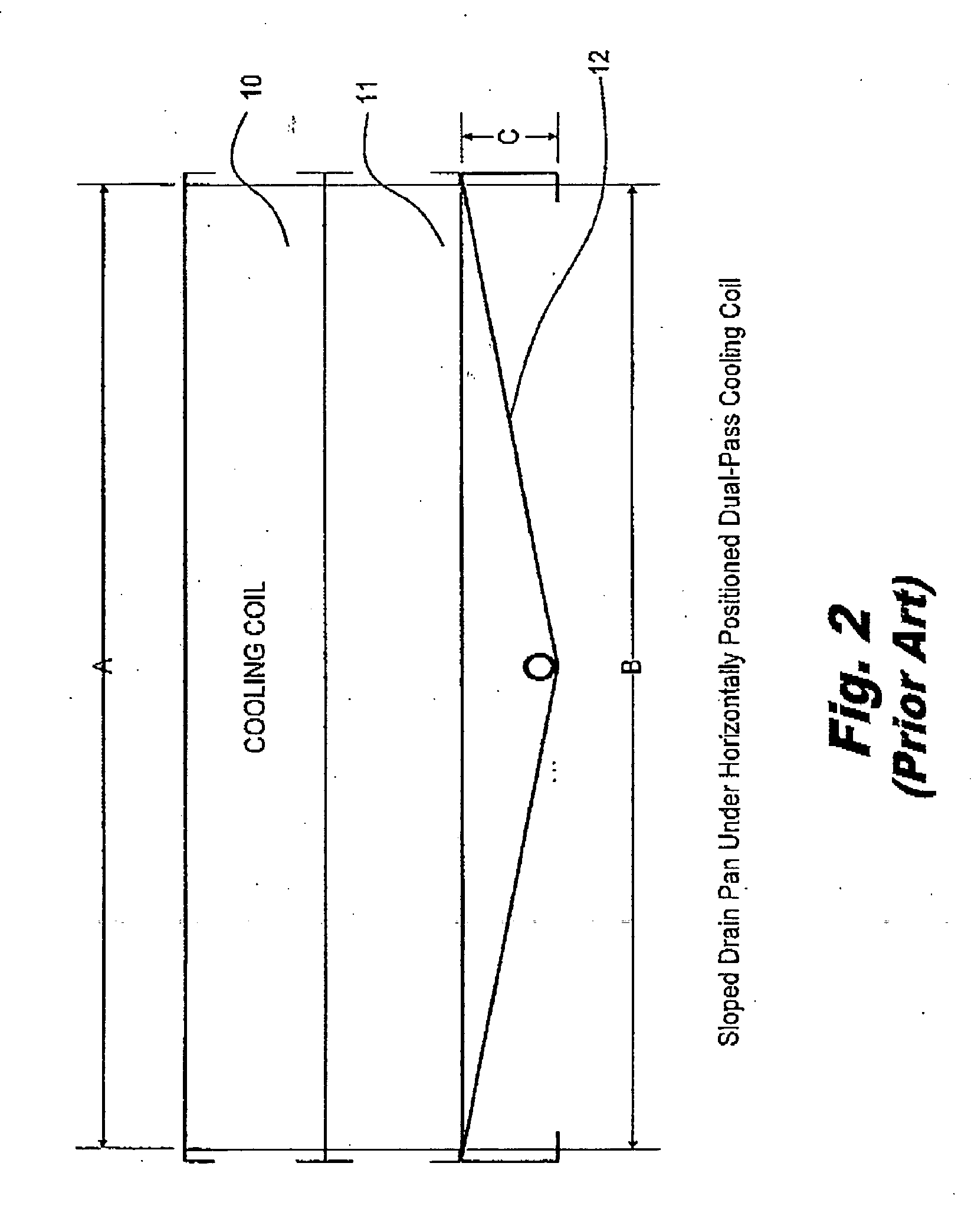
[0038]FIG. 2 shows a prior art horizontal cooling coil 10 being serviced by a drain pan 11 beneath with a sloping bottom of equivalent bottom slope 12 to that of slope 6 shown in FIG. 1. The large size of the required single pan 11 is of equivalent area to the drip area of horizontal cooling coil 10. It is noted that the length “A” of cooling coil 10 (laid horizontally) must equal the width “B” of pan 11. Height dimension “C” of pan 11 is also greater than that of pan 5 in FIG. 1 to maintain the equivalent slope 12. It is also noted t...


PUM


Abstract

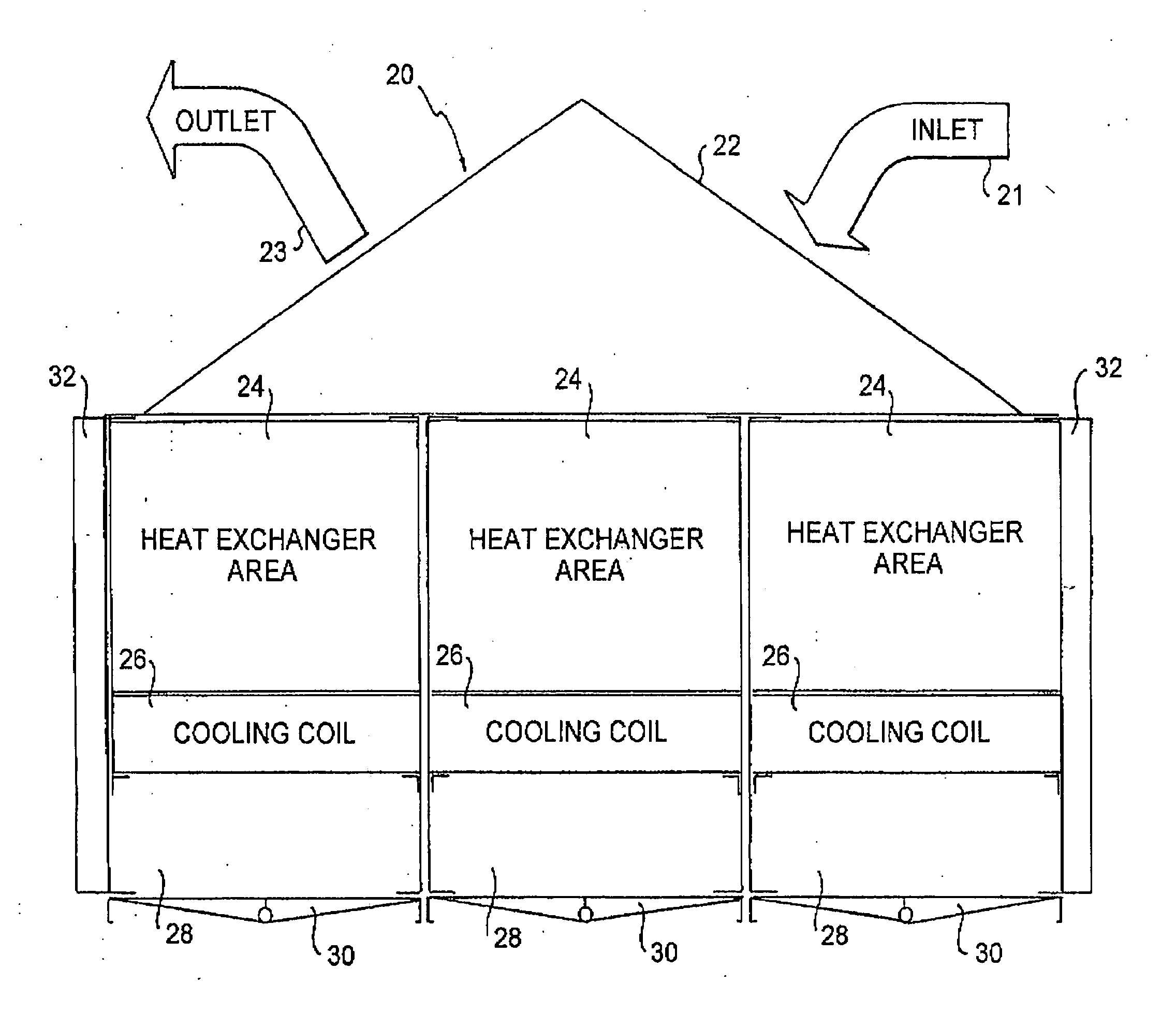
A modular drain pan assembly with one-piece construction, having no seams in the condensate collection area and using multiple small drain pans with drip caps to avoid leakage between individual pans.

Description

RELATED APPLICATIONS[0001]This application is a continuation-in-part of application Ser. No. 13 / 317,660, filed Oct. 25, 2011 and claims priority in part under 35 U.S.C. §120 therefrom, which application is incorporated by reference therefrom.FIELD OF THE INVENTION[0002]The present invention relates to drip pans for substantially horizontally oriented dehumidification cooling coils.BACKGROUND OF THE INVENTION[0003]The purpose of a cooling coil drain pan is to capture condensed water from a cooling coil, and route it to a drain, without leaving areas of stagnant water behind. Drain pans are a potential source of microbial contamination. Until recently, most air handlers and terminal units with cooling coils were designed with flat drain pans. However, ASHRAE Standard 62 now stipulates regarding drain pans that pans intended to collect and drain liquid water shall be sloped at least 0.125 inches per foot or shall be otherwise designed to ensure that water drains freely from the pan whe...

Claims


Application Information

Patent Timeline
Patent Type & Authority Applications(United States)
IPC IPC(8): F25D21/14
CPCF24F13/222F24F2013/227F24F2003/1446
Inventor STARK, WALTER
Owner STARK WALTER
Learn More