Small-scale metal tanks for high pressure storage of fluids

a metal tank and high-pressure storage technology, applied in mechanical equipment, transportation and packaging, transportation items, etc., can solve the problems of difficult to form conventional materials into suitable cylindrical or spherical shapes at the small scale, heavy tanks, and special difficulties, so as to reduce the structural requirements and structure light

Active Publication Date: 2013-04-25
VENTIONS LLC
View PDF3 Cites 8 Cited by
  • Summary
  • Abstract
  • Description
  • Claims
  • Application Information

AI Technical Summary

Benefits of technology

[0013]The creation of such smaller chambers within the pressure vessels reduces the structur

Problems solved by technology

The problem is especially difficult in extremely weight sensitive applications (i.e. rocket engines), and in applications where the pressure of the stored fluid is very high (several hundred pounds per square inch).
The realization of small high-pressure tanks has proved challenging for several reasons including that, given a limitation of minimum gage thickness for conventional materials, the mass of the walls ends up being much higher than what is required, thereby making the tanks much heavier

Method used


Image

  • Small-scale metal tanks for high pressure storage of fluids
  • Small-scale metal tanks for high pressure storage of fluids
  • Small-scale metal tanks for high pressure storage of fluids

Examples


Embodiment Construction

[0042]The following detailed description is merely exemplary in nature and is not intended to limit the invention or the application and uses of the invention. Furthermore, there is no intention to be bound by any expressed or implied theory presented in the preceding technical field, background, brief summary or the following detailed description.

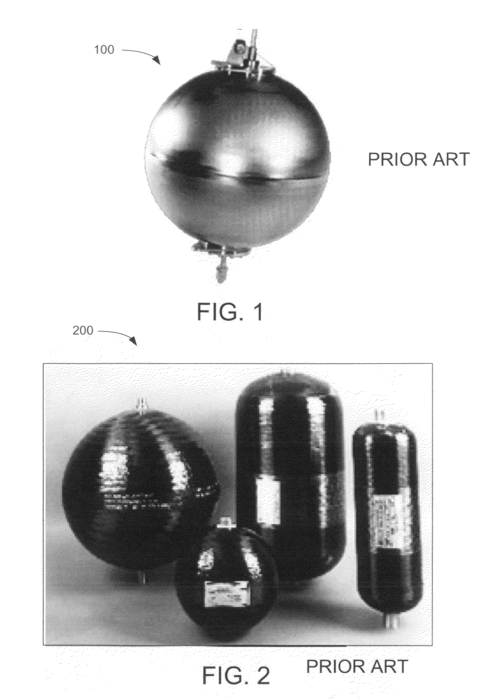
[0043]FIG. 1 is a perspective view illustrating a prior art tank 100 in the 100-10,000 cubic inches volume range. Tank 100 is a spherical tank.

[0044]FIG. 2 is a perspective view illustrating a plurality of prior art tanks 200 in the 100-10,000 cubic inches volume range. Two spherical tanks and two cylindrical tanks with hemispherical tank ends are shown.

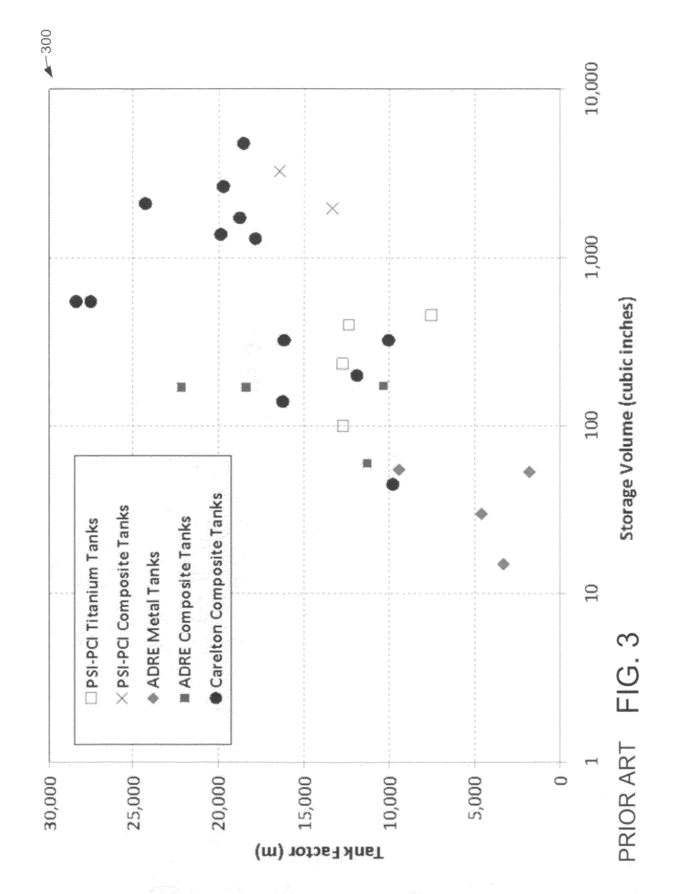
[0045]FIG. 3 is a chart 300 illustrating tank factor vs. storage volume for prior art tanks. The prior art has no tank factors above 3,000 meters for tanks in the 1-10 cubic-inch volume range. The upper volume limit is actually slightly greater than ten cubic inches, as shown. More precisel...


PUM


Abstract

Small scale metal tanks for high-pressure storage of fluids having tank factors of more than 5000 meters and volumes of ten cubic inches or less featuring arrays of interconnected internal chambers having at least inner walls thinner than gage limitations allow. The chambers may be arranged as multiple internal independent vessels. Walls of chambers that are also portions of external tank walls may be arcuate on the internal and/or external surfaces, including domed. The tanks may be shaped adaptively and/or conformally to an application, including, for example, having one or more flat outer walls and/or having an annular shape. The tanks may have dual-purpose inlet/outlet conduits of may have separate inlet and outlet conduits. The tanks are made by fusion bonding etched metal foil layers patterned from slices of a CAD model of the tank. The fusion bonded foil stack may be further machined.

Description

RELATED APPLICATIONS[0001]This application claims the benefit of U.S. Provisional Patent Application Ser. No. 61 / 542,629 filed Oct. 3, 2011 to the same inventor.GOVERNMENT RIGHTS[0002]This invention was made with government support under contract NNA08BB37C awarded by NASA and under contract HR0011-08-C-0101 awarded by DARPA. The government has certain rights in the invention.TECHNICAL FIELD[0003]The present invention generally relates to small storage tanks for fluids, and more particularly relates to small-scale tanks with high tank factors.BACKGROUND[0004]Storage of high pressure gases and liquids is a critical requirement for many applications, e.g. rocket and aircraft propulsion components, automotive airbags, pneumatic and hydraulic systems, etc. The science for design and manufacture of suitable tanks for this purpose is well documented, with many examples of commercially available tanks. Typical tanks are made in the form of spheres or cylinders, and may be manufactured from...

Claims


Application Information

Patent Timeline
IPC IPC(8): F17C1/00
CPCF17C1/00
Inventor LONDON, ADAM
Owner VENTIONS LLC
Why Eureka
Try Eureka