Structure for particle immobilization and apparatus for particle analysis

a technology of structure and particle, which is applied in the direction of material analysis, photoelectric discharge tubes, instruments, etc., can solve the problems of reducing the detection accuracy and the detection accuracy of fluorescence signal intensity, so as to reduce background noise, crosstalk noise or the like

Inactive Publication Date: 2013-04-25
TOSOH CORP
View PDF8 Cites 23 Cited by
  • Summary
  • Abstract
  • Description
  • Claims
  • Application Information

AI Technical Summary

Benefits of technology

[0030]According to the present invention, for example, it is possible to reduce the background noise, the crosstalk noise, or the like is reduced, and optically observe a large number of particles highly sensitively and highly accurately.

Problems solved by technology

This autofluorescence exerts the influence as the background noise, which lowers the detection accuracy of the intensity of the fluorescence signal.
In the second place, when the distance (interval) between the particles is narrow, a problem also arises in relation to the decrease in the detection accuracy caused by the leakage light (crosstalk noise) from the adjacent particle.

Method used


Image

  • Structure for particle immobilization and apparatus for particle analysis
  • Structure for particle immobilization and apparatus for particle analysis
  • Structure for particle immobilization and apparatus for particle analysis

Examples


first embodiment

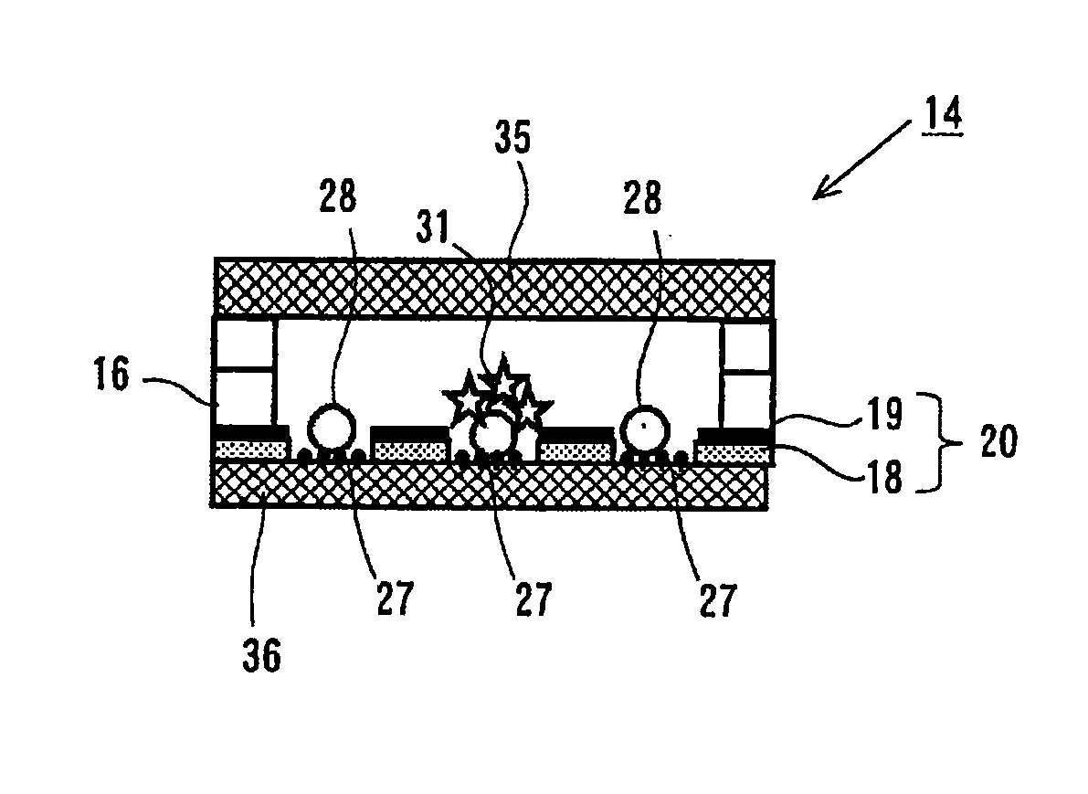
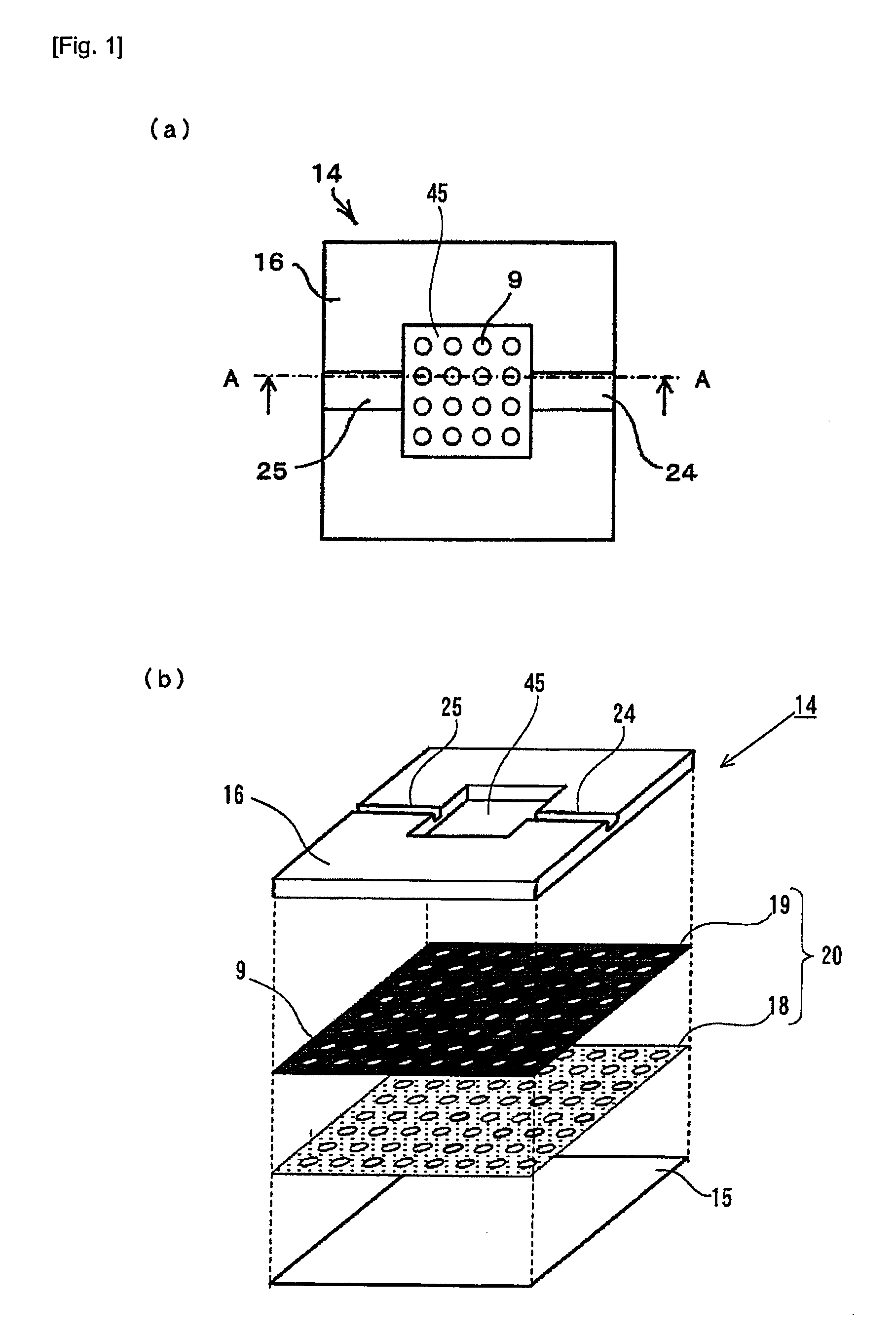
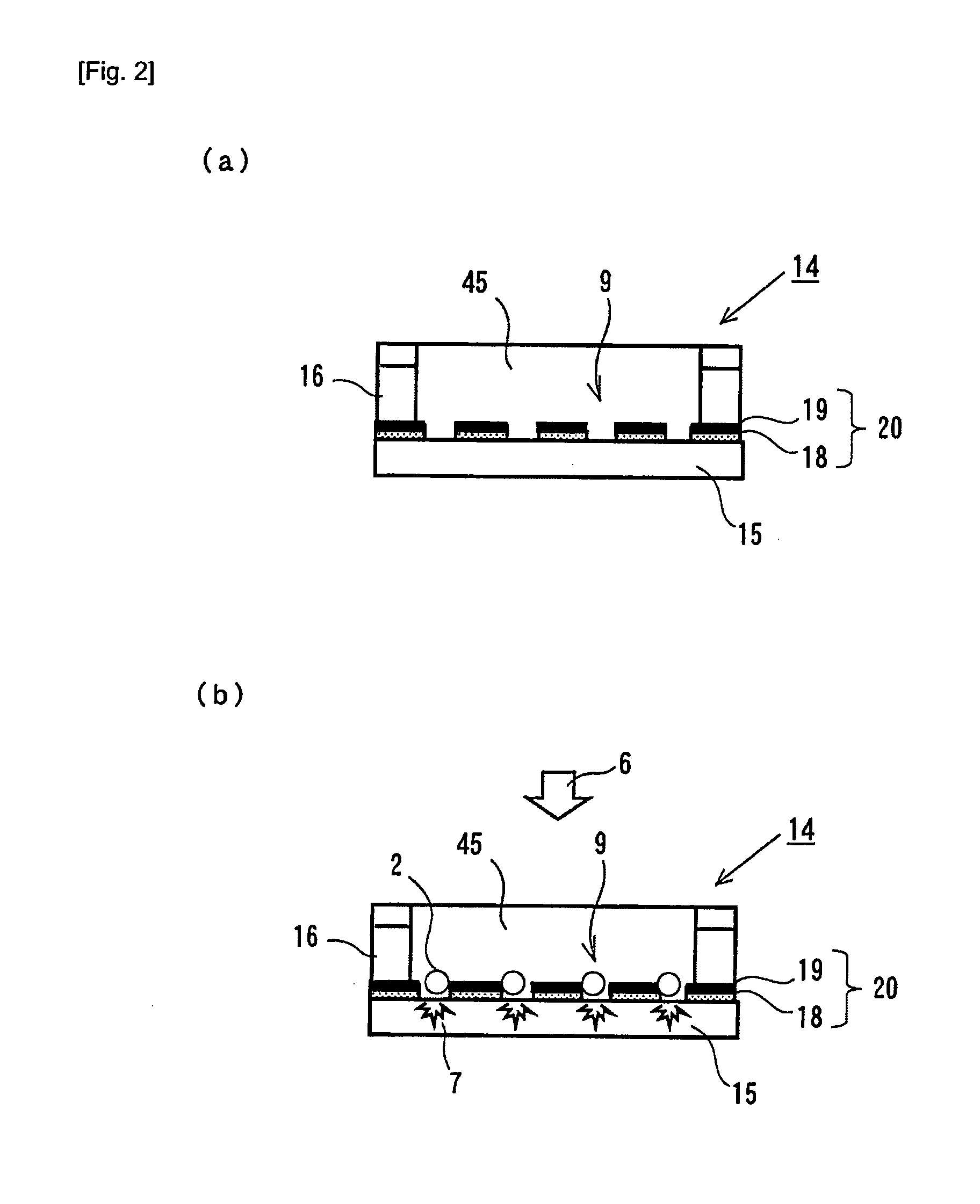
[0089]FIGS. 1 and 2 schematically show the structure according to the first embodiment. FIG. 1(a) shows a plan view of the structure, and FIG. 1(b) shows an exploded perspective view to illustrate the layer structure of the structure. FIG. 2(a) shows a sectional view of in FIG. 1(a) along with A-A, and FIG. 2(b) shows a state where biological samples (for example, cells) are immobilized to the structure.

[0090]As shown in FIGS. 1 and 2, the structure 14 is composed of a flat plate substrate 15, a holding unit 20 which is arranged on the substrate 15, and a spacer 16 for forming, above the holding unit 20, a space (referred to as “accommodating unit” as well) 45 for introducing thereinto a suspension containing the biological sample. The holding unit 20 is composed of a stack of an insulator film 18 and a light shielding film 19. The light shielding film 19 is arranged above the insulator film 18. The holding unit 20 has a plurality of holding holes (through-holes) 9 which are formed ...

second embodiment

[0093]FIGS. 3 and 4 schematically show the configuration of the structure and the particle immobilizing apparatus according to the second embodiment. FIG. 3 shows an exploded perspective view to illustrate the layer structure of the structure, and FIG. 4 shows a sectional view of the structure. FIG. 4 shows a cross section of the same portion as that corresponding to the A-A line shown in FIG. 1(a) (the same hold for sectional views described later on). The structure 14 of the second embodiment has a comb-shaped electrode 21 which is composed of a pair of electrodes 22 and 23 on the holding unit-side surface of the substrate 15. Each of the electrodes 22 and 23 has a plurality of band-shaped electrodes which are arranged in parallel to one another in the direction of arrangement of the holding holes 9. The band-shaped electrodes of one electrode 22 and the band-shaped electrodes of the other electrode 23 are arranged alternately to one another. As shown in FIG. 4, the band-shaped el...

third embodiment

[0094]FIG. 5 shows the structure and the particle immobilizing apparatus according to the third embodiment. The difference from the structure of the second embodiment shown in FIG. 4 resides in that an upper lid 17 which covers the accommodating unit 45 is provided on the spacer 16. The provision of the upper lid 17 is advantageous in that the water content of the suspension containing the biological sample introduced into the accommodating unit 45 can be prevented from being evaporated and the suspension containing the biological sample can be stably supplied from the introducing port 24 into the accommodating unit 45. The reason why the supply of the suspension is stabilized is considered to be because the flow line of a fluid which flows between the upper lid 17 and the accommodating unit 45 of the spacer 16 easily forms a laminar flow parallel to the plane of the substrate. The upper lid can also be provided for the structure of the first embodiment in order to obtain a similar ...


PUM

PropertyMeasurementUnit
thicknessaaaaaaaaaa
thicknessaaaaaaaaaa
contact angleaaaaaaaaaa

Abstract

A structure 14 for particle immobilization has a plurality of holding holes 9 for holding respective test particles in order to detect light emitted from a substance which indicates the presence of a component for constructing each of the test particles, and the structure 14 for particle immobilization comprises a flat plate substrate 15, and a holding unit 20 which is arranged on the substrate 15 and which is formed with the plurality of holding holes 9. In this configuration, a light shielding film 19 which reduces light noise is provided for the substrate 15 or the holding unit 20 in order that the light noise such as the background noise and the crosstalk noise can be reduced, and a large number of test particles can be optically observed highly sensitively and highly accurately.

Description

TECHNICAL FIELD[0001]The present invention relates to a structure for particle immobilization for immobilizing test particles (particles to be tested), and an apparatus for analyzing test particles.BACKGROUND ART[0002]In recent years, a technique has been proposed, in which particles such as biological samples (for example, cells) are arranged on a substrate individually and regularly, and thus it is possible to individually analyze and observe the property and the structure of each of the particles. The technique is expected to be applied in a variety of fields including drug development (drug discovery), medical treatment, examination (inspection), analysis, and so forth. Patent Document 1 discloses a method for immobilizing cells one by one to respective wells by repeatedly performing such a step that a cell suspension is added onto a substrate provided with micropores (microwells) arranged in an array form to wait for the sedimentation of cells into wells, and then cells remaini...

Claims


Application Information

Patent Timeline
Patent Type & Authority Applications(United States)
IPC IPC(8): G01N21/01G01N21/66
CPCG01N21/6454G01N21/66G01N21/01G01N2021/6482
Inventor MOGAMI, TOSHIFUMIMORIMOTO, ATSUSHIFUTAMI, TORU
Owner TOSOH CORP
Why Eureka
Try Eureka