Stator Core For Motor and Manufacturing Method Thereof

a technology of stator core and motor, which is applied in the direction of solid insulation, magnetic circuit shape/form/construction, windings, etc., can solve the problems of poor performance and falling efficiency of motor, and achieve the reduction of air gap of each split core, the effect of improving fixing ability and assembly efficiency

Active Publication Date: 2013-04-25
LG INNOTEK CO LTD
View PDF6 Cites 8 Cited by
  • Summary
  • Abstract
  • Description
  • Claims
  • Application Information

AI Technical Summary

Benefits of technology

[0010]Accordingly, an object of the present invention is to provide the stator core for motor, which has improved structure in order to compose a cylindrical stator core by rolling one integrally formed body, and firmly compose an assembly structure in the assembly units facing each other.
[0017]Preferably, but not necessarily, the hook unit has the rounded edge of which the concavo and convex structure interlocked with each other, and the gapped groove is formed at the position nearby the hook unit to reduce an interference effect during the bending of stator core body.
[0022]The advantage according to the present invention is that the fixing ability and assembly efficiency can be improved because the reliability of assembly part of stator core made by rolling one integrally formed body is improved.
[0023]Further, the combination and transportation for motor is easy and the loss of working following combination error of core unit can be reduced because the air gap of each split cores is minimized during the combination of stator core.

Problems solved by technology

But for the laminating stator core, there is a complication that plural metal plates undergo press working with the same configuration, and then the laminating process should be done separately.
Further for the split core, there is a complication that stator core should be formed as a cylindrical shape by a fitting combination for the connecting part of split core using an extra adhesion or arranging a complementary shape due to an air gap in a assembly position for each split core during a combination process of a cylindrical shaped stator core by combination of each split core after each split core is formed by molding or sintering.
But according to this composition, product defects by the separation of core assembly are mostly likely to occur in a assembly process of stator core after bending, and also there is a problem that if the assembled parts are not firmly fixed, the efficiency for motor can fall or poor performance can occur.

Method used


Image

  • Stator Core For Motor and Manufacturing Method Thereof
  • Stator Core For Motor and Manufacturing Method Thereof
  • Stator Core For Motor and Manufacturing Method Thereof

Examples


Embodiment Construction

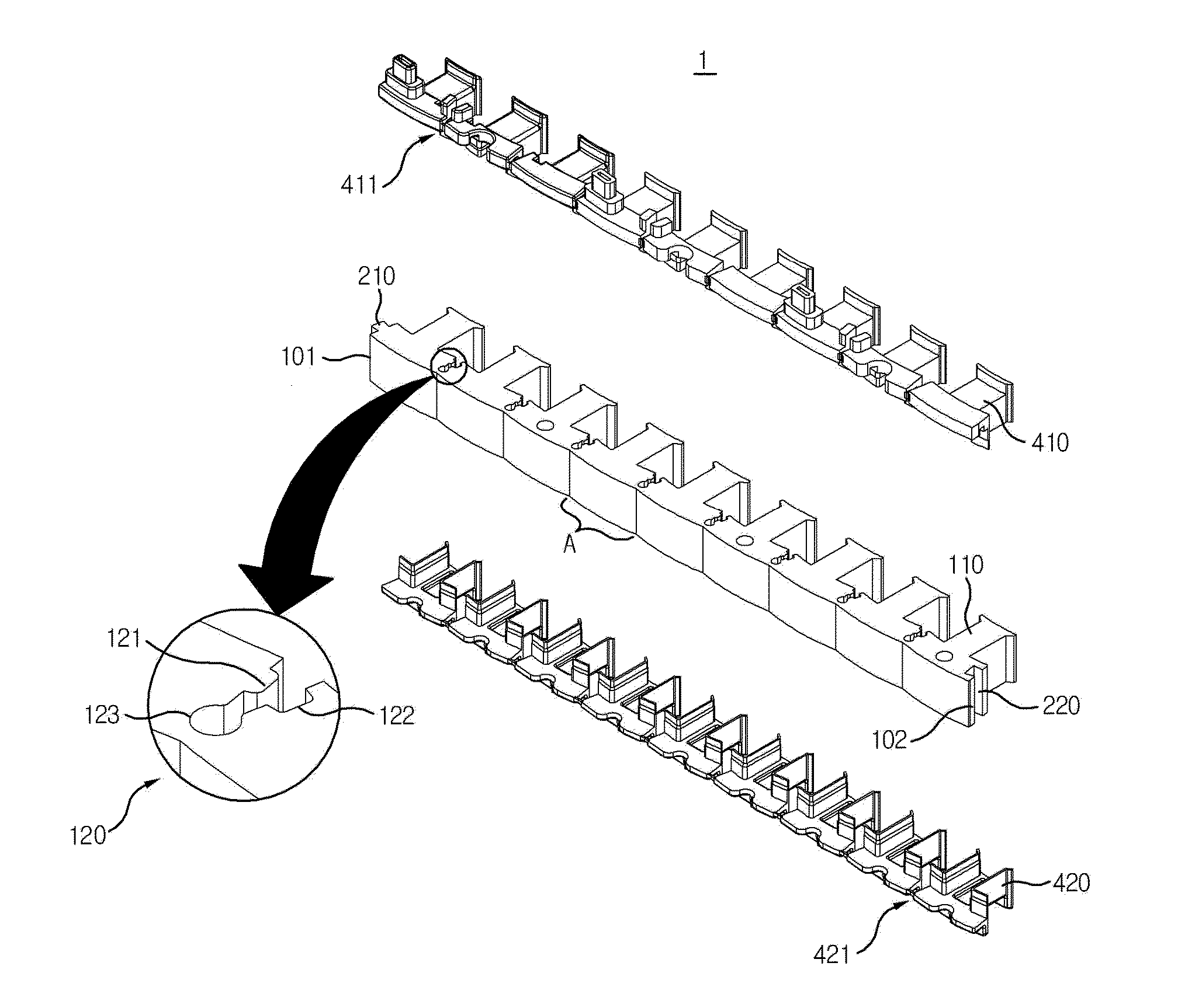
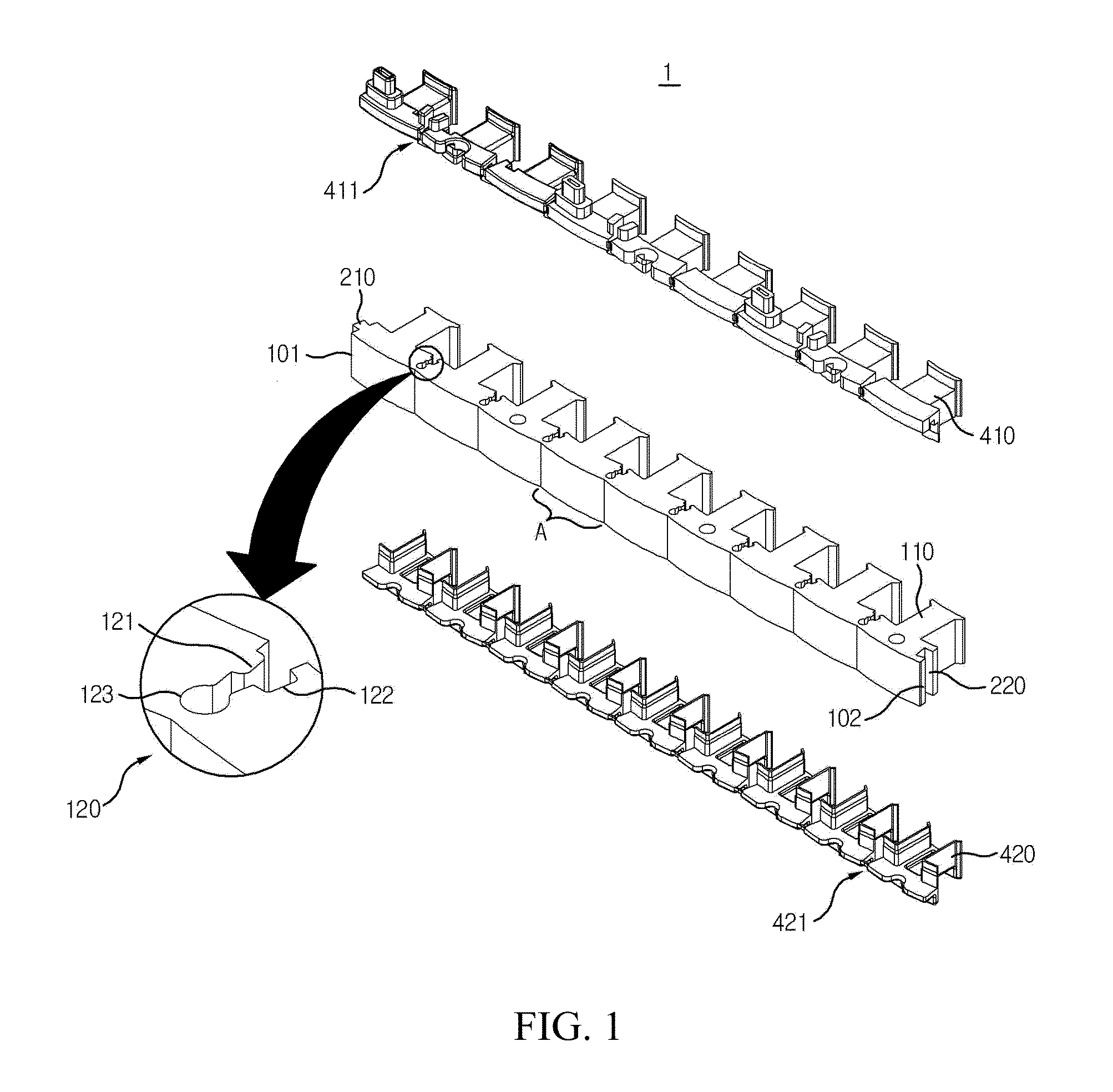
[0033]Hereinafter, the stator core for motor and manufacturing method thereof will be described in detail with reference to the accompanying drawings.

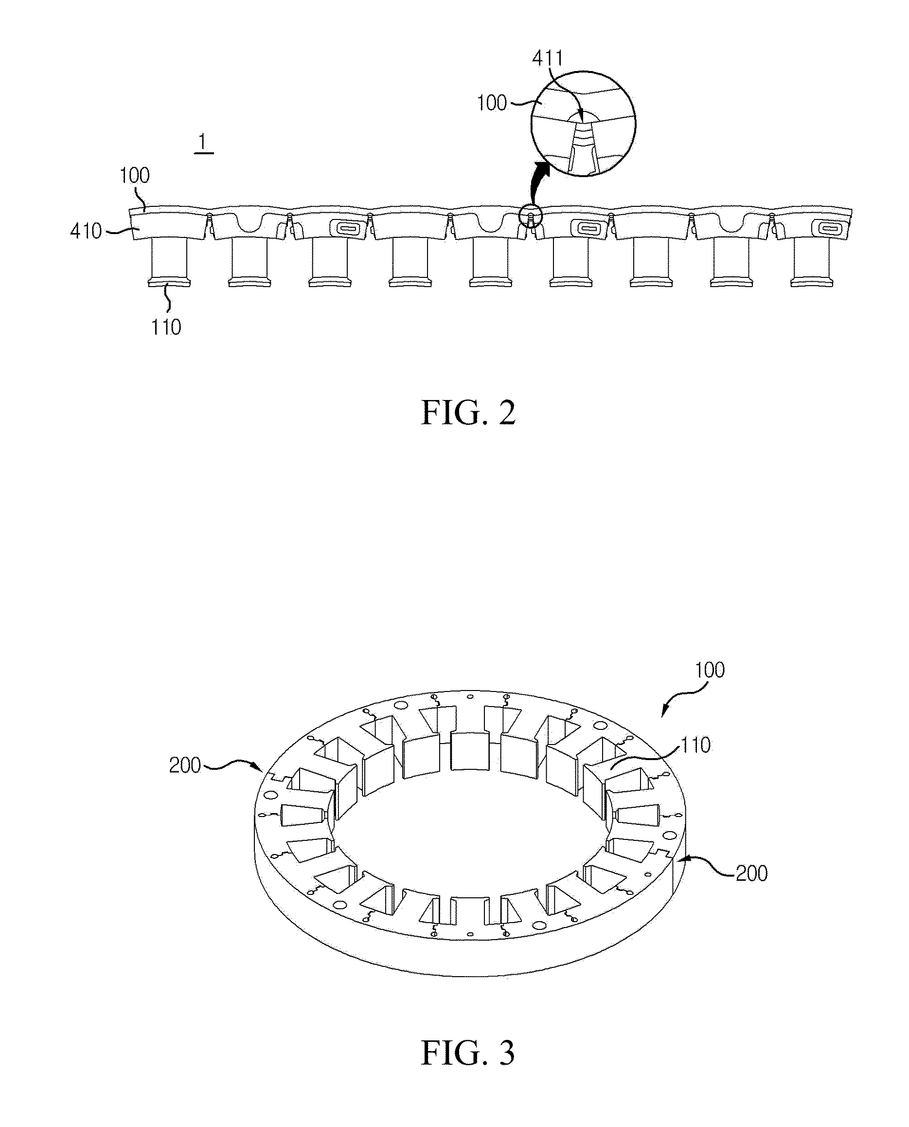
[0034]FIG. 1 is an exploded perspective view illustrating the stator core, the first insulator and the second insulator, and the stator core is formed in a mold and assembled, further, has a state before bending, FIG. 2 is an assembly view of FIG. 1, FIG. 3 is a perspective view illustrating the stator core of FIG. 1, which is bended and is cylindrically rolled, and as a fixing unit according to the first exemplary embodiment of the present disclosure, FIG. 4 is a perspective view illustrating the stator core of FIG. 1, which is bended and is cylindrically rolled, and as a fixing unit according to the second exemplary embodiment of the present disclosure, FIG. 5 is a perspective view illustrating the stator core module of FIG. 1, which is bended and is cylindrically rolled, FIG. 6 is an enlarged view of the teeth for stator core module...


PUM


Abstract

Disclosed stator core for motor is comprising: more than one stator core body; a fixing unit, which is arranged at both ends of the stator core body and fixes the stator core body to be a cylindrical shape; a first insulator, which is integrally formed by mold in order to wrap a part of the stator core body and a side surface of plural teeth simultaneously; and a second insulator, which is arranged to have a form corresponding to the first insulator, and which is integrally formed by mold in order to wrap a part of the stator core body and a side surface of plural teeth simultaneously through the assembly with the first insulator, wherein the first simulator and the second simulator are separated from each other by the section wrapping the teeth during the bending process of the stator core body.

Description

CROSS-REFERENCE TO RELATED APPLICATION[0001]This application claims the benefit under 35 U.S.C. §119 of Korean Patent Application No. 10-2011-0107389, filed Oct. 20, 2011, which is hereby incorporated by reference in its entirety.BACKGROUND[0002]1. Field of the Invention[0003]The present invention relates stator core for motor and manufacturing method thereof.[0004]2. Description of the Related Art[0005]Generally, stator core for motor is formed by coiling plural teeth protruded from an inner circumferential surface after a metal core body is configured as a cylindrical shape.[0006]Recently the stator core needs a miniaturization and weight lightening according to a miniaturization of motor, thus a forming the stator core by laminating a thin metal plate with constant thickness or forming the cylindrical shaped stator core by combining a roughly “T” shaped a split core having one teeth is more often used than a conventional forming method using the stator core of one body.[0007]But ...

Claims


Application Information

Patent Timeline
Patent Type & Authority Applications(United States)
IPC IPC(8): H02K3/34H02K1/12
CPCH02K1/148H02K15/022H02K3/345H02K1/14H02K3/34H02K15/10
Inventor YU, BYEONGJONG
Owner LG INNOTEK CO LTD
Why Eureka
Try Eureka