Low-profile large current inductor

a large current inductor and low-profile technology, applied in the direction of transformer/inductance details, basic electric elements, inductances, etc., can solve the problems of ferrite core rupture and component rupture, and achieve the effect of preventing iron core rupture, eliminating the drawback of wire deviation, and facilitating the height control of the produ

Inactive Publication Date: 2013-04-25
INDUCTEK TECH
View PDF4 Cites 7 Cited by
  • Summary
  • Abstract
  • Description
  • Claims
  • Application Information

AI Technical Summary

Benefits of technology

[0013]The design of the full round fillets of the iron core of the low-profile large current inductor for the passing of the two opposite end portions of the winding avoids wire breaking due to concentration of stress between the wire material of the winding and the iron core when the end portions of the winding are respectively extended out of the respective arched notches and mounted in the two wire-mounting grooves. Further, as the periphery of the iron core is round chamfered, the iron core has no burr or sharp edge and does not require any further roll grinding or surface finishing that may cause iron core damage. Further, the round chamfered periphery of the iron core avoids concentration of stress, preventing iron core rupture.
[0014]Further, the design of the flat bottom surface of each wire-mounting groove facilitates the control of the height of the product and eliminates the drawback of wire deviation of the conventional U-groove or V-groove design that affects the control of the product flatness and height.
[0015]Further, the octagonal configuration of the expanded upper part of the iron core lowers the stress concentration point of the iron core, preventing product internal crack during tin soldering.
[0016]Further, the design of the arched notches of the ex

Problems solved by technology

However, as the drum-type ferrite core has sharp edges around the periphery that may cause stress concentration, resulting

Method used


Image

  • Low-profile large current inductor
  • Low-profile large current inductor
  • Low-profile large current inductor

Examples


Embodiment Construction

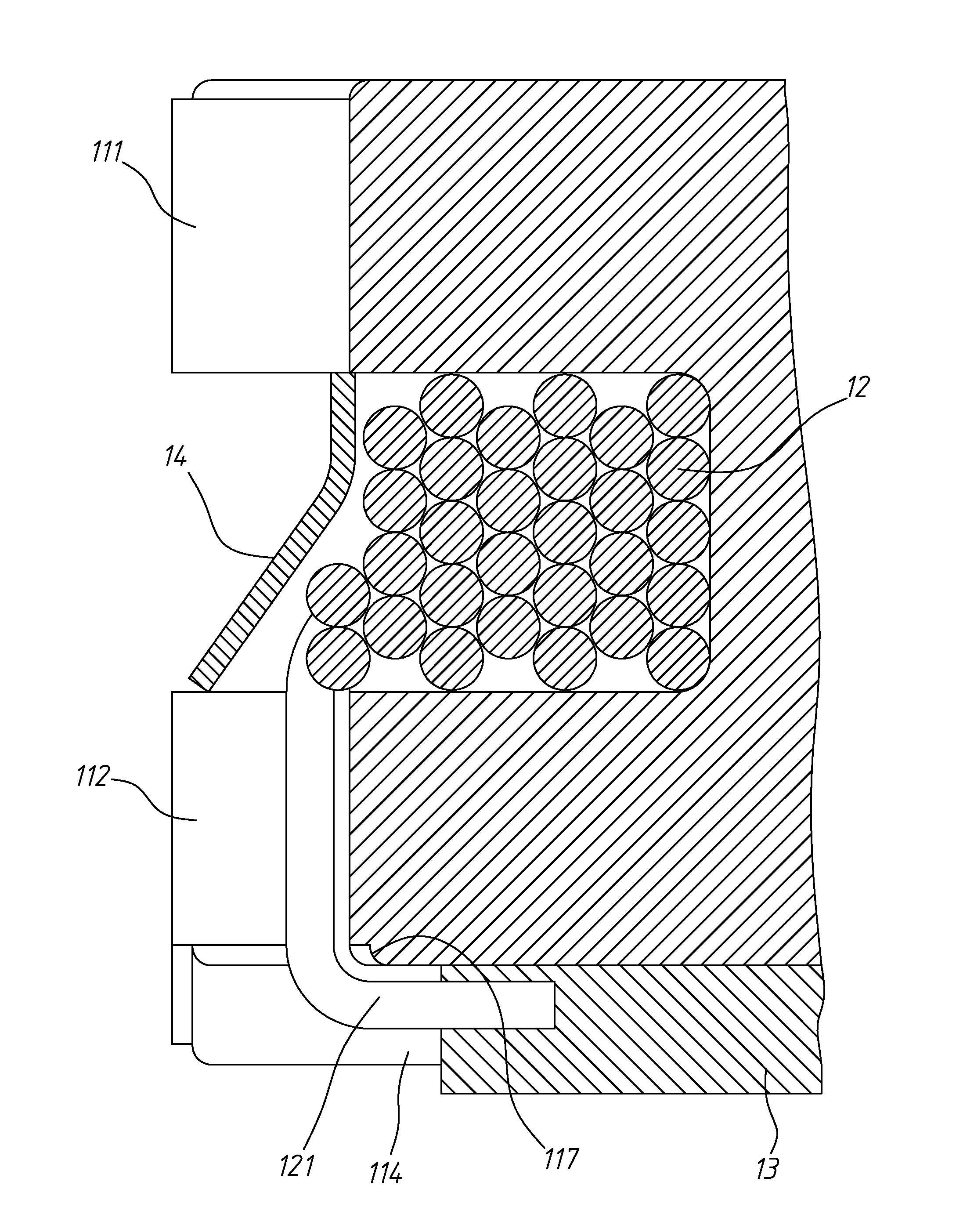
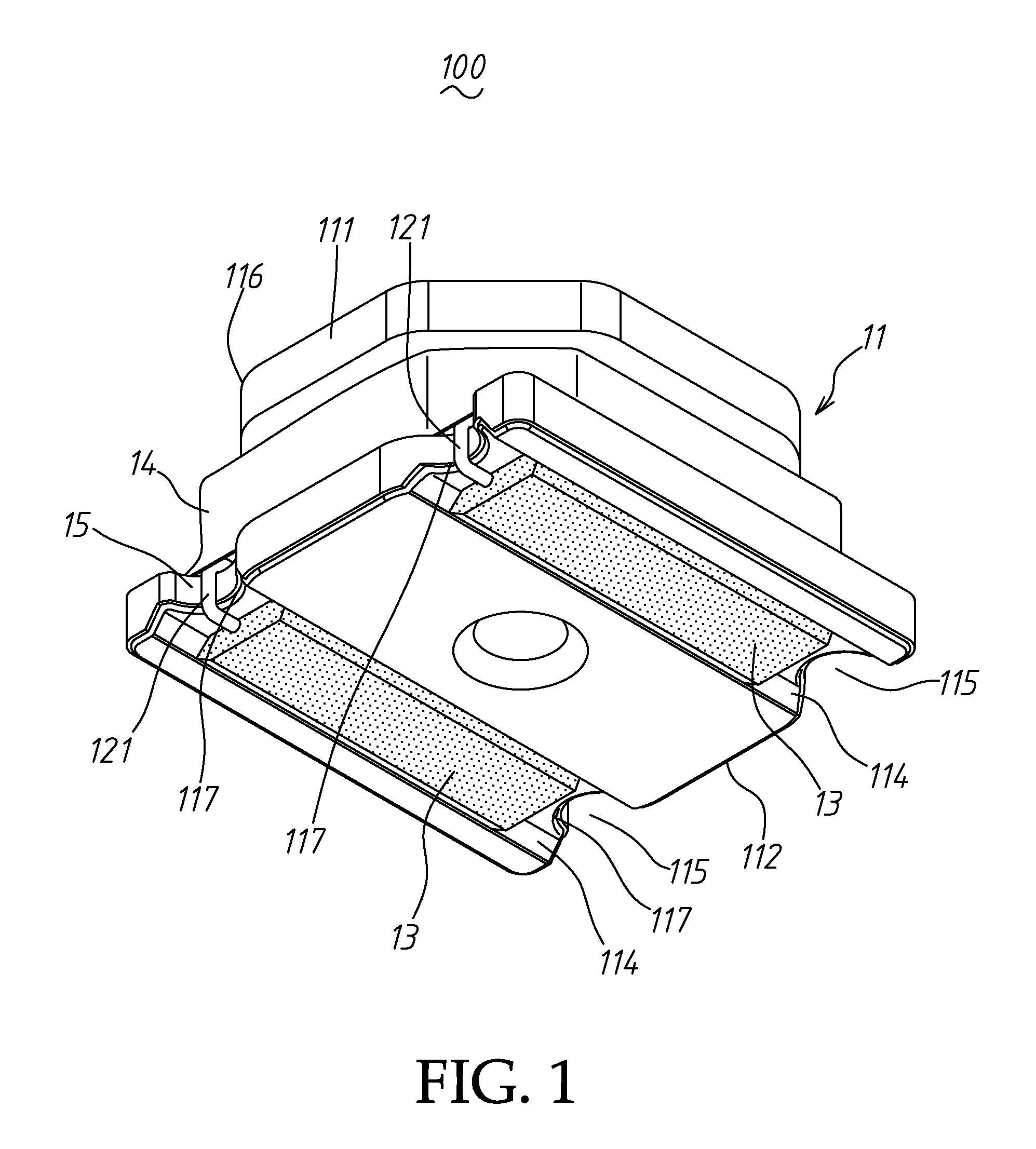
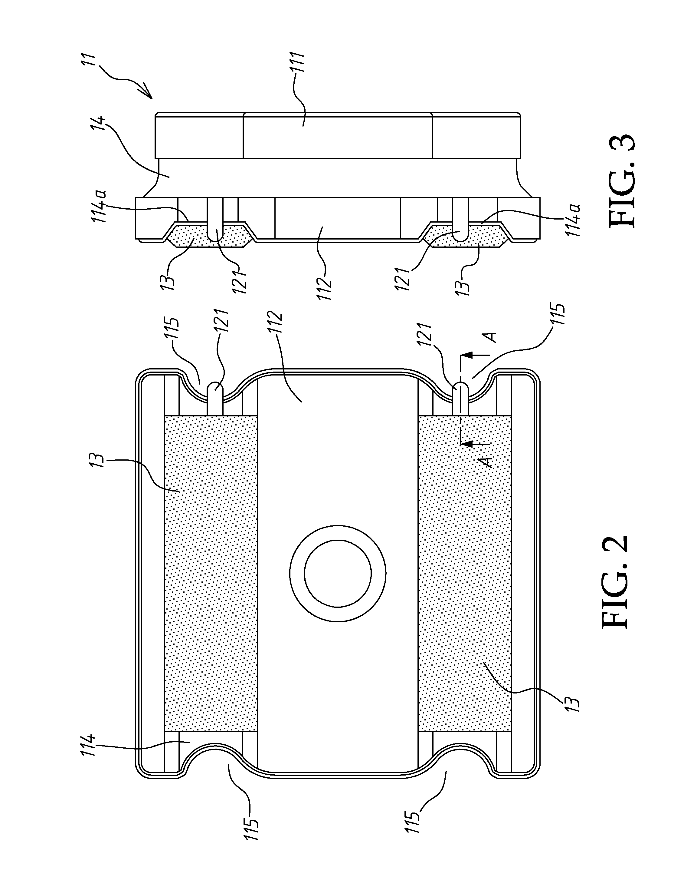
[0023]Referring to FIGS. 1˜4, a low-profile large current inductor 100 in accordance with the present invention is shown comprising an iron core 11, a winding 12, two flat electrodes 13 and a magnetic coating 14.

[0024]The iron core 11, as shown in FIG. 5, comprises an expanded upper part 111, an expanded lower part 112, a core shank 113 connected between the expanded upper part 111 and the expanded lower part 112, two wire-mounting grooves 114 extending across the bottom wall of the expanded lower part 112 in a parallel manner, and a plurality of arched notches 115 respectively located on the expanded lower part 112 at each of the two distal ends of each of the two wire-mounting grooves 114. Further, each wire-mounting groove 114 defines a flat bottom surface 114a, as shown in FIG. 5(B).

[0025]In this embodiment, the expanded upper part 111 of the iron core 11 has an octagonal shape, as shown in FIG. 5(C). The four corners of the expanded upper part 111 corresponding to the four arch...


PUM


Abstract

A low-profile large current inductor includes an iron core having an expanded upper part, an expanded lower part, a core shank connected between the expanded upper part and the expanded lower part, two wire-mounting grooves extending across the bottom wall of the expanded lower part in a parallel manner and four arched notches respectively located on the expanded lower part at each of two distal ends of each of the two wire-mounting grooves, a winding wound round the core shank of the iron core with two end portions thereof respectively extended through the arched notches into the wire-mounting grooves, two flat electrodes respectively attached to the wire-mounting grooves and respectively connected with the end portions of the winding, and a magnetic coating surrounding the winding. The iron core has full round fillets in corner areas thereof for the passing of the two opposite end portions of the winding.

Description

BACKGROUND OF THE INVENTION[0001]1. Field of the Invention[0002]The present invention relates to inductor technology and more particularly, to an innovative design of low-profile large current inductor, which is practical for use in mobile electronic products.[0003]2. Description of the Related Art[0004]An inductor is a passive electrical component used to remove noises, suppress transient current, reduce EMI (electromagnetic interference) and convert power. Inductors are widely used in a variety of electronic products. An inductor is usually constructed as a winding of conducting material, typically copper wire, wrapped around a core for raising or lowering the voltage. For use in a mobile electronic product, such as smart cell phone, tablet PC or notebook computer that has light, thin, short and small characteristics, electronic components must be made having a low profile characteristic.[0005]Taiwan Patent I 301989 discloses a winding component design, entitled “Surface-mounting ...

Claims


Application Information

Patent Timeline
IPC IPC(8): H01F27/04
CPCH01F27/292H01F17/045
Inventor LIANG, KUO-WANGFU, WEN-LANGFAN, MEI-CHU
Owner INDUCTEK TECH
Why Eureka
Try Eureka