High luminance multicolor illumination devices and related methods and projection system using the same

Active Publication Date: 2013-04-25
APPOTRONICS CORP LTD
View PDF6 Cites 25 Cited by
  • Summary
  • Abstract
  • Description
  • Claims
  • Application Information

AI Technical Summary

Benefits of technology

[0018]Advantages of the illumination device according to embodiments of the present invention have the following advantages. By introducing a second type of light sources in addition to a narrow band light source, a highly saturated narrow band light and a less saturated wide band light are simultaneously output, and the spectrum width is broa

Problems solved by technology

However, it is very inefficient to generate highly saturated color using lamps that emit white light.
Also, such a method can only achieve a limited number of color lights, and it is difficult to achieve a continuous transition from color to color.
However, the mixed color light and mixed white light often look unnatural and their color renderings are often unsatisfactory.
The problem comes from the fact that the three highly saturated primary lights have narrow spectra, and the spectrum of the mixed light has peaks and valleys, which is very different from the spectrum of sun light 110.
However, because of the large spectrum overlap between white ligh

Method used


Image

  • High luminance multicolor illumination devices and related methods and projection system using the same
  • High luminance multicolor illumination devices and related methods and projection system using the same
  • High luminance multicolor illumination devices and related methods and projection system using the same

Examples


first embodiment

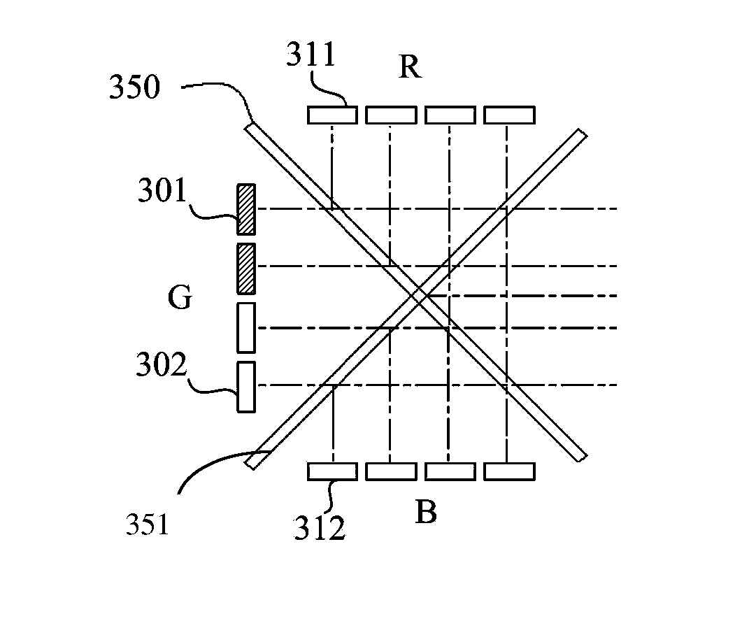
[0045]FIG. 3 illustrates a schematic view of an illumination device according to the present invention. The illumination device includes red (R), green (G) and blue (B) primary color channels whose light are combined by an X-shaped dichroic filter set including filters 350, 351. In the illustrated embodiment, the dichroic filter 350 reflects red light and transmits green and blue lights, and the dichroic filter 351 reflects blue light and transmits green and red lights. As a result, the combined light containing red, green and blue lights is output to the right of the dichroic filter set 350, 351 in FIG. 3. In this embodiment, the red and blue channels include red LEDs 311 and blue LEDs 312, respectively, emitting narrow band red and blue lights.

[0046]In conventional technologies, the green channel only includes green LEDs. To broaden the spectrum of the green channel, in this embodiment, the green channel includes two types of light sources, where the first green light source gener...

second embodiment

[0052]In this embodiment, by introducing the green phosphor LEDs 301, the light of the green channel has a broadened spectrum, which is wider than the spectrum of the green LED light by more than 10 nm. Further, by independently controlling the two green lights, the output green light of the green channel is adjustable between the vivid narrow band color and the soft wide band color. Alternatively, the wide band output green light can be achieved by using two narrow band green lights, as generally described earlier and as will be illustrated by the example of the second embodiment described below.

[0053]In a second embodiment of the present invention, the illumination device employs two red LEDs as examples of two narrow band light sources. As shown in FIG. 6a, the spectrum of the light generated by the first red LEDs is 601, whose spectrum width FWHM is 15 nm; the spectrum of the light generated by the second red LEDs is 602, whose spectrum width FWHM is also 15 nm, but the peak wav...

third embodiment

[0059]To make the two blue lights in blue channel and two red lights in red channel respectively closer to being perceived as “the same color”, preferably, the dominant wavelengths of the two red lights are less than 35 nm apart, the dominant wavelengths of the two blue lights are less than 15 nm apart. The generation of wide band yellow light is used as an example below to explain how wide band combined light is generated in the illumination device of the A wide band yellow light is formed by combining a wide band red light and a wide band green light. Thus, the red phosphor LEDs 513 and the green phosphor LEDs 514 are turned on, while other light sources are turned off. The emission spectra of the red phosphor LEDs 513 and green phosphor LEDs 514 are shown in FIG. 8. After passing through the dichroic filter set 550 / 551, both spectra experience certain loss. This is because the two spectra shown in FIG. 8 have a range of overlap, which leads to losses in the combining process usi...


PUM


Abstract

An illumination device and a projection system using the same. The illumination device includes two or more color channels each including one or more light sources for generating a color light. At least one of the color channels includes light sources of a first type for generating a first (narrow band) light and light sources of a second type for generating a second light. The dominant wavelengths of the first and second lights are within 50 nm of each other, and the width of the combined spectrum (sum of normalized spectra of the first and second lights) is greater than the width of the spectrum of the first light by at least 10 nm. A wavelength-based light combiner is used to combine the color lights from the color channels into a combined light

Description

[0001]This application claims priority under 35 USC §119(e) from U.S. Provisional Patent Application No. 61 / 549,906, filed Oct. 21, 2011, which is herein incorporated by reference in its entirety.[0002]This application also claims priority from China patent application No. 201110345905.9, filed Nov. 4, 2011, which is herein incorporated by reference in its entirety.BACKGROUND OF THE INVENTION[0003]1. Field of the Invention[0004]The present invention is in the technical field of illumination devices. More particularly, the present invention is in the technical field of multicolor illumination devices and projection systems using the same.[0005]2. Description of the Related Art[0006]Narrow band light sources, such as laser diodes (LDs) and light emitting diodes (LEDs), emit light with a narrow wavelength-band. Such narrow band lights are typically highly saturated in color, which can produce much more vivid colors than those usually seen in nature. Wide band light sources, such as tho...

Claims


Application Information

Patent Timeline
IPC IPC(8): F21V9/16F21V9/00
CPCG02B27/149G03B33/06G03B21/204G03B21/2013
Inventor LI, YIZHANG, QUANYANG, YIHU, FEI
Owner APPOTRONICS CORP LTD
Why Eureka
Try Eureka