Self-Adjusting Device for Controlling the Clearance Between Rotating and Stationary Components of a Thermally Loaded Turbo Machine

Active Publication Date: 2013-04-25
ANSALDO ENERGIA SWITZERLAND AG
View PDF6 Cites 35 Cited by
  • Summary
  • Abstract
  • Description
  • Claims
  • Application Information

AI Technical Summary

Benefits of technology

[0030]One of numerous aspects of the present invention includes a self-adjusting device for controlling the clearance, which can avoid disadvantages of prior art devices,

Problems solved by technology

Contact between these parts during operation may lead to damage or even destruction of the entire engine.
However, due to the different geometrical dimensions, materials and heat capacities of blading, housings, and shafts during warm-up (start-up) or cool-down (shut-down) of the engine, the minimum hot clearance may not appear at the hot steady-state condition, where the minimum clearances are des

Method used


Image

  • Self-Adjusting Device for Controlling the Clearance Between Rotating and Stationary Components of a Thermally Loaded Turbo Machine
  • Self-Adjusting Device for Controlling the Clearance Between Rotating and Stationary Components of a Thermally Loaded Turbo Machine
  • Self-Adjusting Device for Controlling the Clearance Between Rotating and Stationary Components of a Thermally Loaded Turbo Machine

Examples


Embodiment Construction

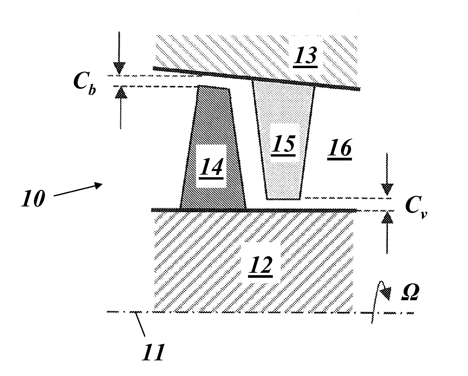
[0055]The present disclosure is directed to the application of a self-adjusting device or system (SAS), including bimetal and / or a shaped memory alloy (SMA) systems and / or any other material, which deforms in an elastic, super-elastic or pseudo-elastic manner above a threshold value of temperature, pressure or mechanical loading. The systems may be actively or passively triggered. They are installed within the assembly section of a turbine- or a compressor blade, a stator- or a rotor heat-shield, a vane-carrier or other rotating or stationary components assembled to the rotor or outer casing of a turbo machine aiming to minimize the clearances during operation.

[0056]In the following, the assembly of a turbine stator heat shield within a stator is chosen as an exemplary application, but the disclosure is not limited to heat shields only.

[0057]The compensation for thermal expansions inside the engine is carried out by attaching driving elements or SAS members to the heat shields surro...


PUM


Abstract

A self-adjusting device (25) for controlling the clearance (C), especially in the radial direction, between rotating and stationary components (21, 23) of a thermally loaded turbo machine, changes clearance (C) in a linear and/or non-linear way during transition of the machine between standstill and steady-state operation. Simple and effective control can be achieved, even in the case of a nonlinear variation of the clearance during transitional operation, by the self-adjusting device (25) including at least two different driving elements (A, B) to move the rotating and fixed components (21, 23) relative to each other in order to change the clearance (C) between them, and by the different driving elements (A, B) being configured to be activated at different times during the transition of the machine.

Description

[0001]This application claims priority under 35 U.S.C. 119 to Swiss App. No. 01551 / 11, filed 19 Sep. 2011, the entirety of which is incorporated by reference herein.BACKGROUND[0002]1. Field of Endeavor[0003]The present invention relates to the technology of turbo machines, such as compressors or gas turbines, or others. It relates more specifically to a self-adjusting device for controlling the clearance, especially in a radial direction, between rotating and stationary components of a thermally loaded turbo machine.[0004]2. Brief Description of the Related Art[0005]Minimization of clearances, particularly radial ones between stationary and rotating parts of a turbo machine, e.g., steam- or gas turbines, jet-engines, compressors, and turbochargers, during operation is essential for minimizing flow-losses and subsequently maximizing the efficiency of such engines.[0006]For illustrative purposes, FIG. 1 shows an example of a turbine configuration, the turbo machine stage 10 including ...

Claims


Application Information

Patent Timeline
IPC IPC(8): F01D11/00
CPCF01D11/00F01D11/18Y02T50/671F05D2300/505F03G7/065F01D11/22Y02T50/60
Inventor SZWEDOWICZ, JAROSLAW LESZEKMOZHAROV, ALEXEYSCHIEDECK, FLORIANBOETTCHER, JONAS
Owner ANSALDO ENERGIA SWITZERLAND AG
Why Eureka
Try Eureka