
Control apparatus for rotating machine

a control apparatus and rotating machine technology, applied in the direction of electronic commutators, motor/generator/converter stoppers, dynamo-electric converter control, etc., can solve the problems of ac rotating machine instability, increase in troubles, wire breaking, etc., to achieve reliably and stably started up and controlled, weaken control

Active Publication Date: 2013-05-02
MITSUBISHI ELECTRIC CORP
View PDF28 Cites 22 Cited by
  • Summary
  • Abstract
  • Description
  • Claims
  • Application Information

AI Technical Summary

Benefits of technology

The present invention includes a calculator that can measure the speed of an AC rotating machine during stable control and start-up control. The invention also corrects the current controls to ensure that the voltage commands are consistent with the power converter's maximum output voltage. This prevents overmodulation and ensures reliable and stable starting and control of the AC rotating machine.

Problems solved by technology

However, the rotor position sensor is relatively bulky, which has imposed restriction on its arrangement, and caused bothersome work of connecting control transmission wires for transmitting the sensor output to the control apparatus and an increase in troubles such as wire breaking.
However, the rotor position of the AC rotating machine cannot be found before starting up the inverter; in particular, when the AC rotating machine is rotating at high speed, thereby generating a reverse voltage of high amplitude, undesired torque sometimes has been produced due to unstable current control when restarting the inverter, and in the worst case, the restart has also become unable due to overcurrent protection function.

Method used


Image

  • Control apparatus for rotating machine
  • Control apparatus for rotating machine
  • Control apparatus for rotating machine

Examples


embodiment 1

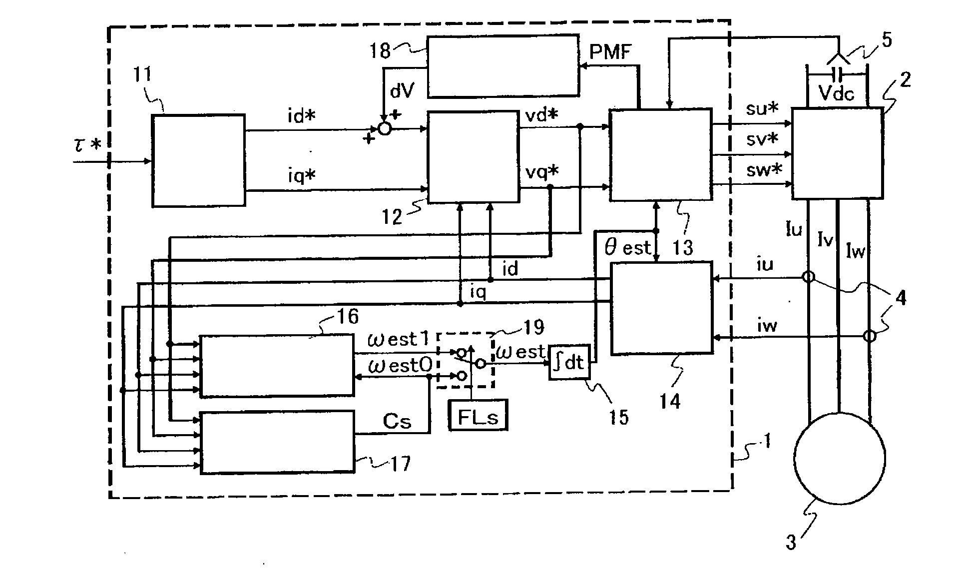
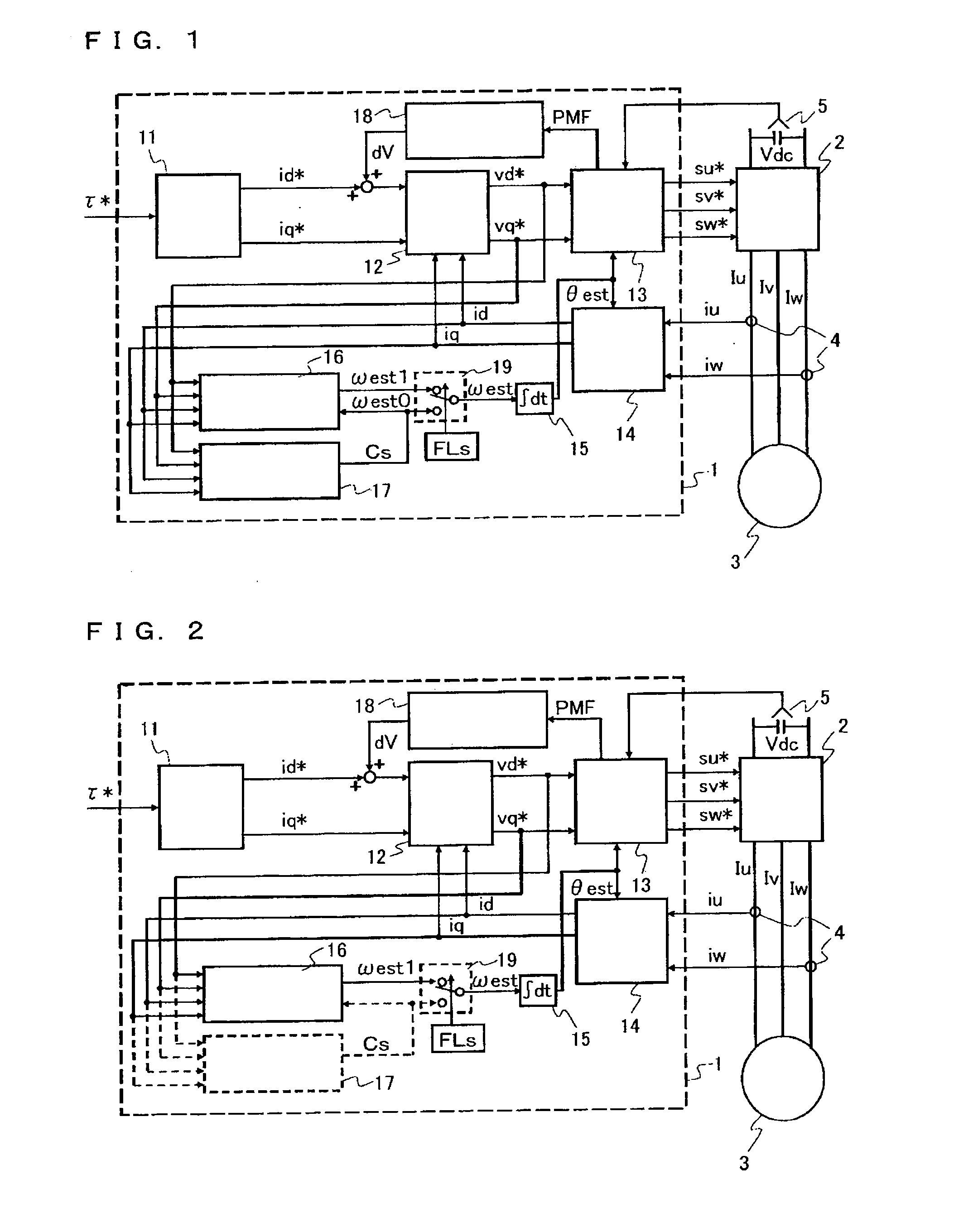
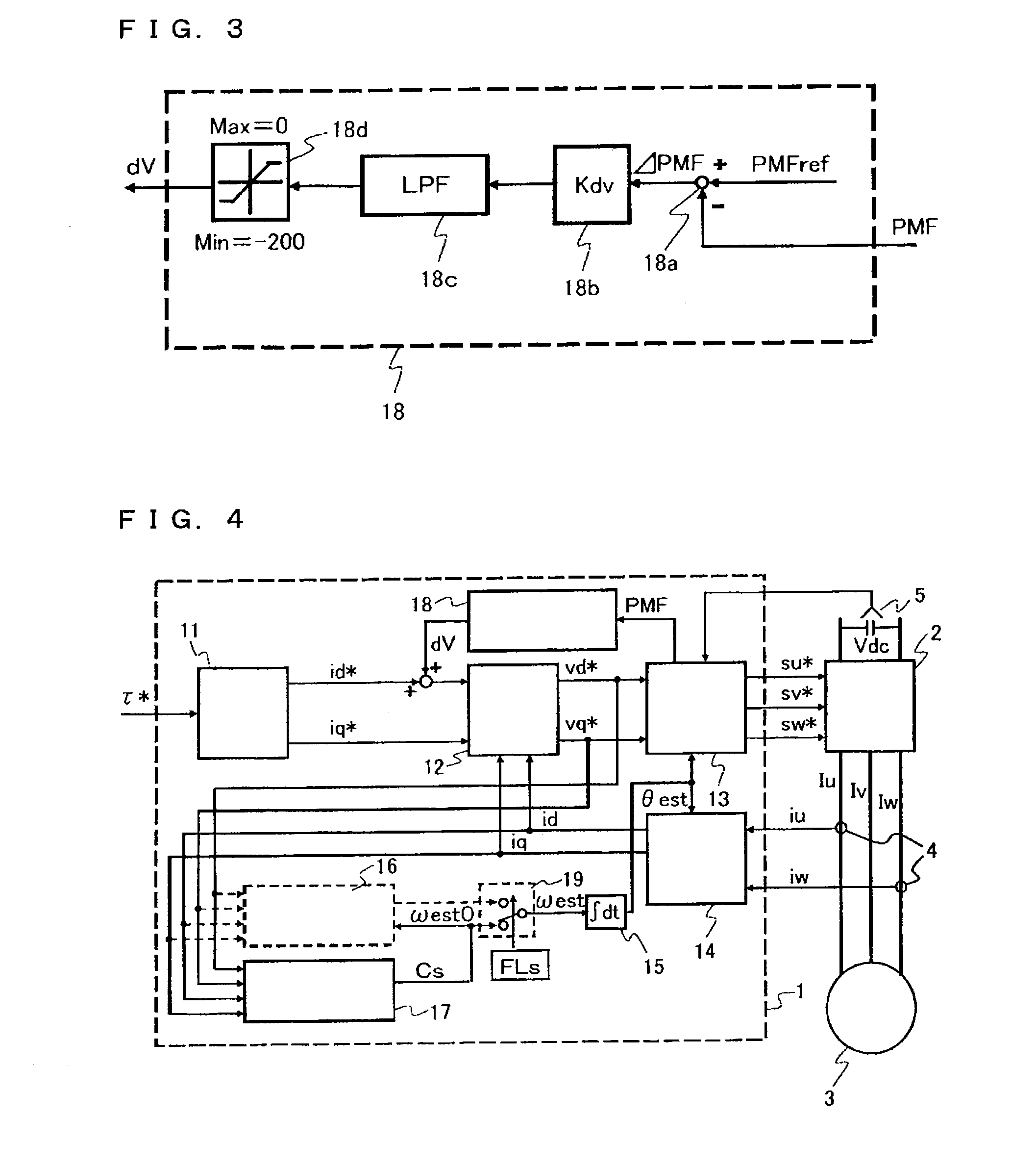
[0018]FIG. 1 is a block diagram of a control apparatus for an AC rotating machine according to Embodiment 1 of the present invention; FIG. 2 is a block diagram of the control apparatus for an AC rotating machine in steady state control; and FIG. 4 is a block diagram of the control apparatus for an AC rotating machine in start-up control. In FIG. 1, the control apparatus for an AC rotating machine drives and controls an AC rotating machine 3, which comprises a control circuit 1, a power converter (inverter) 2, a current detector 4, and a voltage detector 5.

[0019]The control circuit 1 is a controller that produces voltage commands vd* and vq* based on current commands id* and iq*, and switching commands su*, sv* and sw* based on the voltage commands vd* and vq*. The power converter 2 is, for example, a three-phase power converter that performs power conversion between DC power and three-phase AC power, which generates an AC voltage based on the switching commands su*, sv* and sw*, and...

embodiment 2

[0054]FIG. 7 is a block diagram of a control apparatus for an AC rotating machine according to Embodiment 2 of the invention. In FIG. 7, Embodiment 2 differs from Embodiment 1 in that a starting-phase setting unit 22 is provided in a control circuit 21. Other than that, the configuration is the same as that of Embodiment 1; parts with the same reference numerals as those in FIG. 1 are the same or corresponding ones. The starting-phase setting unit 22 calculates an energization-start rotation phase θ0 of the AC rotating machine 3 when the start-up control is started based on the detection currents iu and iw that are AC currents flowing through the AC rotating machine 3.

[0055]FIG. 8 shows a configurational example of the starting-phase setting unit 22. The starting-phase setting unit 22 shown in FIG. 8 is configured to output the energization-start rotation phase θ0 at the start of the start-up control is started, from the detection currents iu and iw on the rotational coordinates. Mo...


PUM


Abstract

A control apparatus for an AC rotating machine that can reliably and stably start up an AC rotating machine, particularly a synchronous motor using a permanent magnet, in position-sensorless vector control thereof, includes: a steady speed calculator that calculates, during steady state control of the AC rotating machine, a rotation angular frequency of the AC rotating machine based on an AC current and voltage commands; and a start-up speed calculator that calculates, during start-up control within a predetermined period after the AC rotating machine has been started up, the rotation angular frequency of the AC rotating machine based on the AC current and the voltage commands. The control apparatus corrects during the start-up control current commands so that the AC voltage amplitude of the voltage commands will be a constant value not more than the maximum output voltage of a power converter.

Description

TECHNICAL FIELD[0001]The present invention relates to a control apparatus for an AC rotating machine that controls a synchronous motor with a permanent magnet by an inverter without using a position sensor.BACKGROUND ART[0002]Until now, a control apparatus for an AC rotating machine, when output torque from the AC rotating machine is accurately controlled, has needed to be equipped with a rotor position sensor in order to allow a current to flow into the AC rotating machine based on a rotor position of the machine. However, the rotor position sensor is relatively bulky, which has imposed restriction on its arrangement, and caused bothersome work of connecting control transmission wires for transmitting the sensor output to the control apparatus and an increase in troubles such as wire breaking. In contrast to this, what is called sensorless vector control has already been put into practical use, which enables the rotor position to be indirectly estimated by detecting an induction vo...

Claims


Application Information

Patent Timeline
Patent Type & Authority Applications(United States)
IPC IPC(8): H02P6/20H02P1/46H02P6/06H02P6/08H02P6/18H02P6/182H02P6/28
CPCH02P21/0032H02P21/0042H02P6/205H02P2203/05H02P2203/09H02P21/146H02P21/18H02P21/26H02P21/34
Inventor KATO, SHOYAMASAKI, HISANORIHATANAKA, KEITAKITANAKA, HIDETOSHIYAMASHITA, YOSHINORI
Owner MITSUBISHI ELECTRIC CORP
Learn More