Stereoscopic image display

a stereoscopic image and display technology, applied in the field of stereoscopic image display, can solve the problems of serious 3d crosstalk, low luminance of 3d images, and low luminance of 2d/3d images, so as to reduce the decrease in aperture ratio, improve data charging characteristics, and increase the luminance of a display image

Active Publication Date: 2013-05-02
LG DISPLAY CO LTD
View PDF2 Cites 5 Cited by
  • Summary
  • Abstract
  • Description
  • Claims
  • Application Information

AI Technical Summary

Benefits of technology

[0012]An aspect of this document is to provide a stereoscopic image display capable of improving data charging characteristics and minimizing decrease in aperture ratio, which can increase the luminance of a display image in a 2D mode and widen the vertical viewing angle in a 3D mode by dividing each pixel into a main display section and an active black stripe.

Problems solved by technology

Thus, the luminance of the 3D images is low, and serious 3D crosstalk may occur depending on the synchronization between the display device and the liquid-crystal shutter glasses and the on / off switching response characteristic.
However, the black stripes formed on the patterned retarder may lower the luminance of 2D / 3D images, and they may interact with the black matrixes, causing moiré.
An increase in the gate-drain parasitic capacitance Cgd may result in a large RC (resistance and capacitance) delay of a pixel, thus deteriorating the data charging characteristics of the pixel.
However, this may reduce the aperture ratio of a pixel.

Method used


Image

  • Stereoscopic image display
  • Stereoscopic image display
  • Stereoscopic image display

Examples


Embodiment Construction

[0032]Hereinafter, implementations of this document will be described in detail with reference to the attached drawings. The same reference numerals will be used throughout to designate the same or like components. In describing the present invention, if a detailed explanation for a related known function or construction is considered to unnecessarily divert the gist of the present invention, such explanation will be omitted.

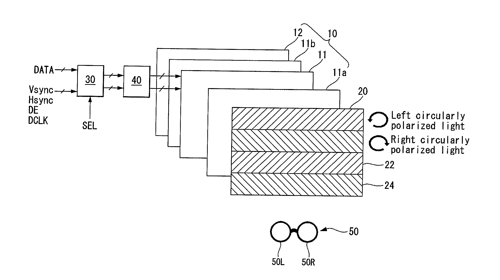
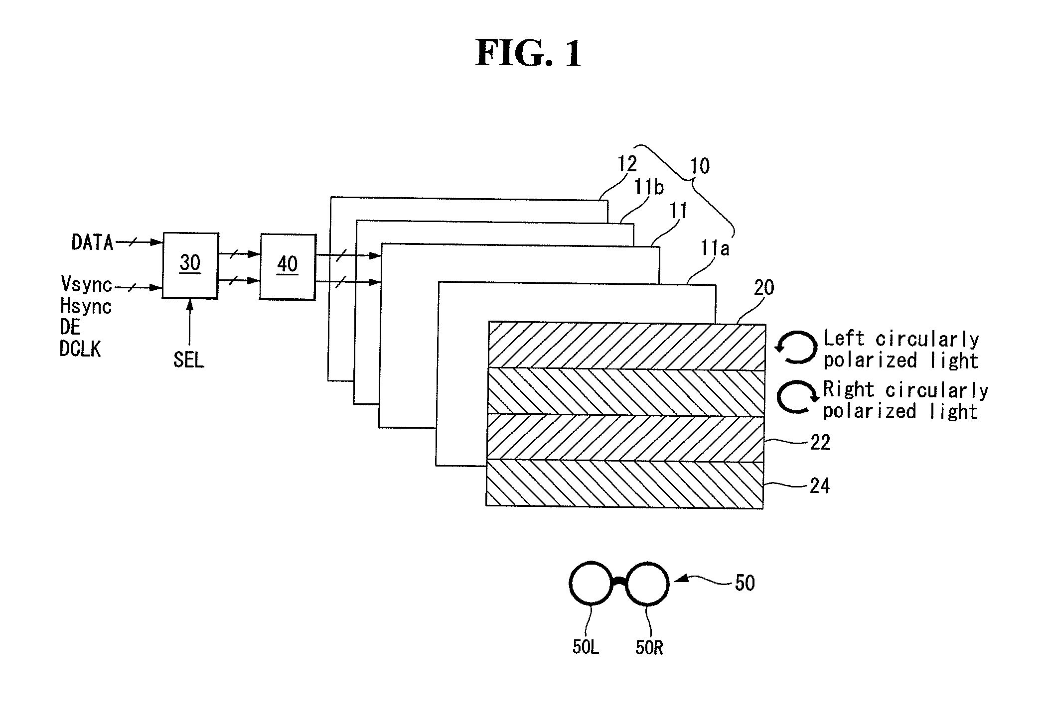
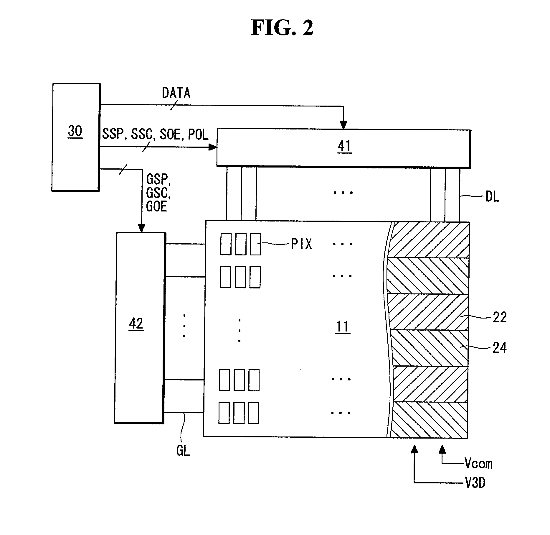
[0033]FIGS. 1 to 5 are views showing the structure and operating principle of a stereoscopic image display according to an exemplary embodiment of the present invention.

[0034]With reference to FIGS. 1 to 5, the stereoscopic image display of the present invention comprises a display device 10, a pattern retarder 20, a controller 30, a panel driving circuit 40, and polarization glasses 50.

[0035]The display device 10 may be implemented as a flat panel display device such as liquid crystal display (LCD), field emission display (FED), plasma display panel (PDP), elec...


PUM


Abstract

A stereoscopic image display according to an embodiment includes: a main display section including a first liquid crystal cell connected to a data line through a first switch TFT and connected to a common line supplied with a common voltage and a first storage capacitor; and an auxiliary display section including a second liquid crystal cell connected to the data line through a second switch TFT and connected to the common line through a discharge control TFT and a second storage capacitor.

Description

[0001]This application claims the priority benefit of Korean Patent Application No. 10-2011-0109795 filed on Oct. 26, 2011 in Republic of Korea, the entire contents of which are incorporated herein by reference for all purposes as if fully set forth herein.BACKGROUND[0002]1. Field[0003]This document relates to a stereoscopic image display[0004]2. Related Art[0005]Methods of implementing 3D images of a stereoscopic image display may be classified into a stereoscopic technique and an autostereoscopic technique.[0006]The stereoscopic technique is implemented using a time difference image of left and right eyes having the most reliable three dimensional effects. The stereoscopic technique is classified into a glasses method and a non-glasses method. The non-glasses method is a method in which, generally, an optical plate, such as a parallax barrier, for separating the optical axes of left and right parallax images is installed in front or rear of a display screen. The glasses method dis...

Claims


Application Information

Patent Timeline
Patent Type & Authority Applications(United States)
IPC IPC(8): G06T15/00G02B30/25
CPCH04N13/0434H04N13/0452G02F2001/134345G02F1/136227G02F1/136213G02F1/134345H04N13/337H04N13/356G02F1/13
Inventor KIM, SEOKHWANG, KWANGJO
Owner LG DISPLAY CO LTD
Why Eureka
Try Eureka