Strain measurement apparatus, linear expansion coefficient measurement method, and correction coefficient measurement method for temperature distribution detector

a measurement method and temperature distribution technology, applied in the direction of instruments, measurement devices, electrical devices, etc., can solve the problems of inability to find the stress caused by thermal strain in the apparatus, affecting the service life length, and the above-described three-dimensional configuration measurement apparatus is not capable of measuring the strain. , to achieve the effect of finding the correction coefficien

Active Publication Date: 2013-05-02
TOYOTA JIDOSHA KK
View PDF7 Cites 17 Cited by
  • Summary
  • Abstract
  • Description
  • Claims
  • Application Information

AI Technical Summary

Benefits of technology

[0009]The invention provides a strain measurement apparatus capable of easily measuring strain corresponding to the stress caused by thermal strain in a constrained object, a linear expansion coefficient measurement method, and a correction coefficient measurement method for a temperature distribution detector.
[0011]According to the strain measurement apparatus having the foregoing configuration, the first stereo image and the second stereo image of the measurement object are produced by the stereo camera device. Then, the three-dimensional configuration of the measurement object is found from the first stereo image and the second stereo image, and therefore the actual strain of the measurement object is found. Furthermore, the temperature distribution in the measurement object is detected by the temperature distribution detector, and the free thermal strain of the measurement object is found from the detected temperature distribution. Furthermore, a difference obtained by subtracting the found free thermal strain from the found actual strain is found as constraint strain of the measurement object. Therefore, the constraint strain of the measurement object, which is the strain corresponding to the stress caused by thermal strain in a constrained object, can easily be measured.
[0012]That is, in the strain measurement apparatus in accordance with the first aspect of the invention, the difference obtained by subtracting the free thermal strain, which is the strain of the measurement object resulting from free expansion caused by heat, from the actual strain, which is the actual strain of the measurement object, is defined as the “constraint strain” of a measurement object, and the thus-defined “constraint strain” is measured as an index for evaluating the service life length of the measurement object affected by thermal fatigue. Then, the strain measurement apparatus finds the actual strain from the first stereo image and the second stereo image produced by the stereo camera device, and finds the free thermal strain from the temperature distribution in the measurement object detected by the temperature distribution detector. Therefore, the strain measurement apparatus can easily measure the “constraint strain”, which is the difference obtained by subtracting the free thermal strain from the actual strain.
[0014]According to the linear expansion coefficient measurement method having the foregoing configuration, the test piece that is made of the same material as the measurement object and that is provided with marks formed at at least two positions is uniformly heated to a pre-set temperature, and is disposed at substantially the same position as that of the measurement object. Then, the distance between two of the marks formed on the test piece is found, and the linear expansion coefficient is found from the found distance between the two marks. Therefore, by using the above-described strain measurement apparatus, a relationship between the temperature of the measurement object and the linear expansion coefficient of the measurement object can easily be found (see FIGS. 7 to 9).
[0018]According to the strain measurement apparatus in accordance with the first aspect of the invention, the first stereo image and the second stereo image of the measurement object are produced by the stereo camera device. Then, a three-dimensional configuration of the measurement object is found from the first stereo image and the second stereo image, and then the actual strain is found. Furthermore, the temperature distribution in the measurement object is detected by the temperature distribution detector, and the free thermal strain is found from the detected temperature distribution. Still further, the difference obtained by subtracting the found free thermal strain from the found the actual strain is found as the constraint strain. Therefore, the constraint strain can easily be measured. This effect is also obtained by the strain measurement method in accordance with the fourth aspect of the invention.

Problems solved by technology

With regard to component parts, such as an exhaust manifold or the like, of an exhaust system of an engine mounted on a vehicle, it is known that since the exhaust gas discharged from the engine has high temperature, thermal strain causes stress to occur, which affects the service life length.
However, although the three-dimensional configuration measurement apparatus described in JP 2009-270915 A is capable of measuring the strain of a measurement object, the apparatus is not capable of finding the stress caused by thermal strain.
That is, the above-described three-dimensional configuration measurement apparatus is not capable of measuring the strain that corresponds to the aforementioned stress (the stress caused by thermal strain) that affects the service life of a measurement object.

Method used


Image

  • Strain measurement apparatus, linear expansion coefficient measurement method, and correction coefficient measurement method for temperature distribution detector
  • Strain measurement apparatus, linear expansion coefficient measurement method, and correction coefficient measurement method for temperature distribution detector
  • Strain measurement apparatus, linear expansion coefficient measurement method, and correction coefficient measurement method for temperature distribution detector

Examples


Embodiment Construction

[0034]Embodiments of the invention will be described hereinafter with reference to the drawings.

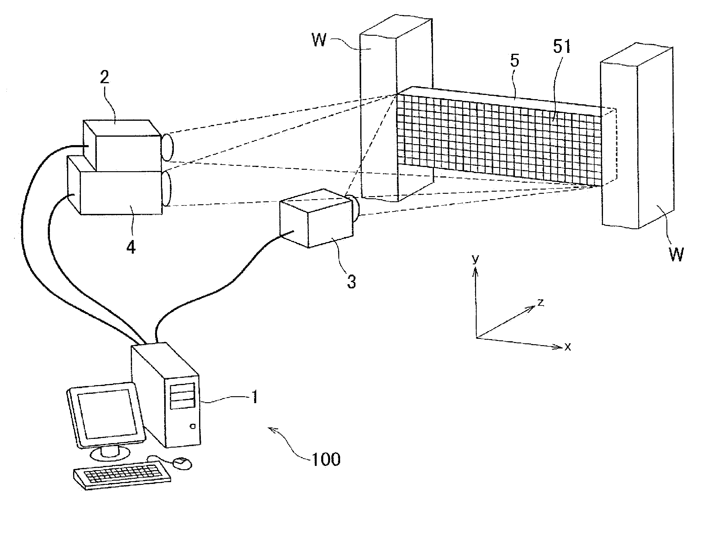
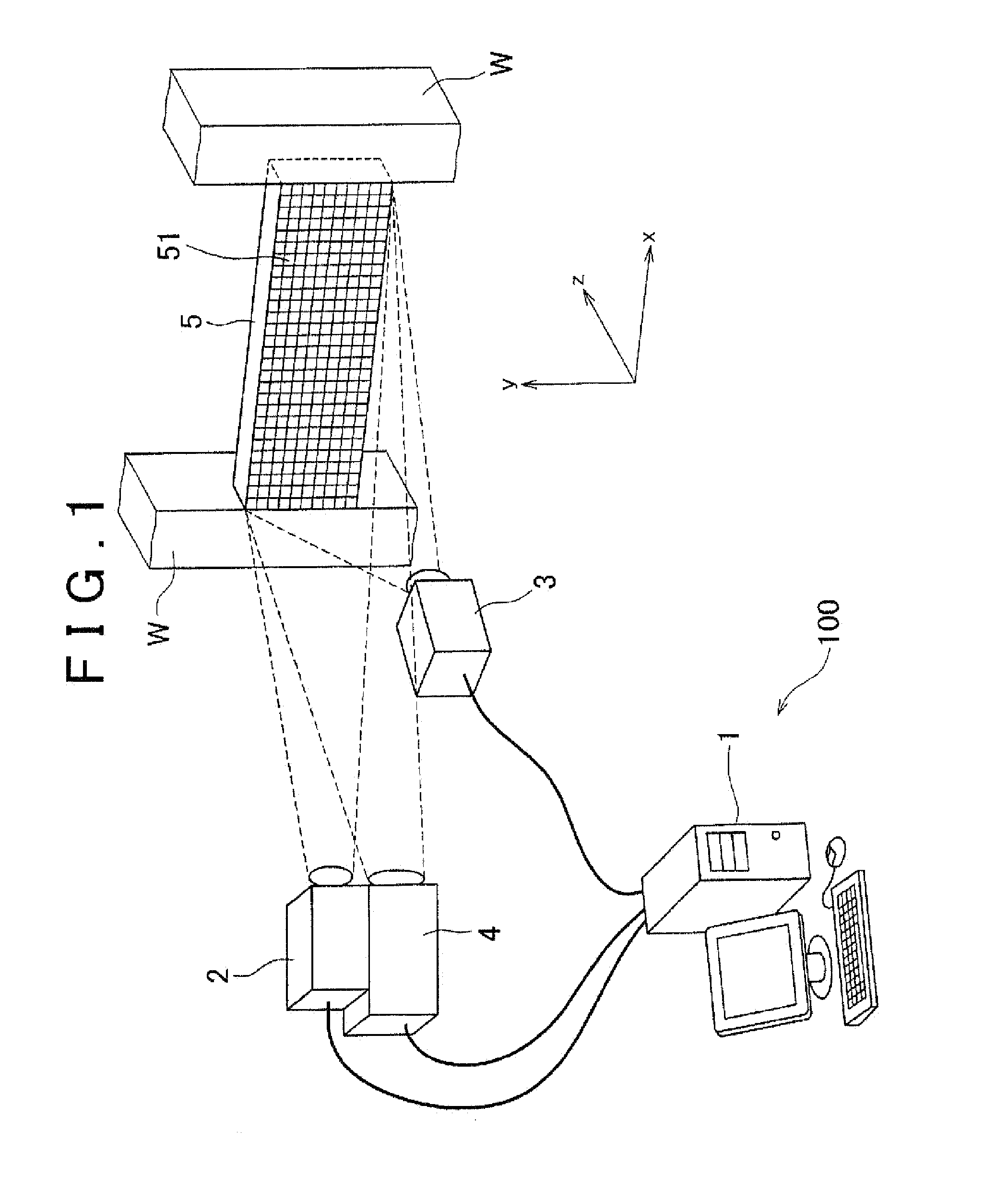
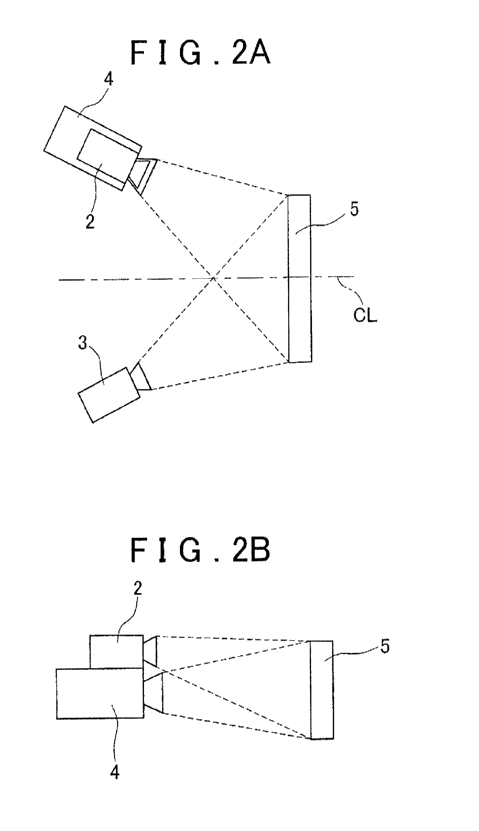
[0035]Firstly, with reference to FIGS. 1, 2A and 2B, a configuration of a strain measurement apparatus in accordance with an embodiment of the invention will be described. FIG. 1 is a configuration diagram showing an example of a strain measurement apparatus 100 in accordance with the embodiment of the invention. FIG. 2A is a plan view of the strain measurement apparatus 100 shown in FIG. 1, and FIG. 2B is a side view of the strain measurement apparatus 100 shown in FIG. 1.

[0036]The strain measurement apparatus 100 measures as a constraint strain εr of a measurement object 5 a difference obtained by subtracting a free thermal strain εt of the measurement object 5 that is a strain of free expansion caused by heat from an actual strain α that is a strain that actually occurs in the measurement object 5. As shown in FIG. 1, the strain measurement apparatus 100 includes a computer 1, a first ...


PUM


Abstract

A strain measurement apparatus includes: a stereo camera device that produces a first stereo image and a second stereo image of a measurement object; an actual strain calculation portion configured to find a three-dimensional configuration of the measurement object from the first stereo image and the second stereo image to find actual strain of the measurement object; a temperature distribution detector that detects a temperature distribution of the measurement object; a free thermal strain calculation portion configured to find free thermal strain of the measurement object from the temperature distribution detected by the temperature distribution detector; and a constraint strain calculation portion configured to find as constraint strain of the measurement object a difference obtained by subtracting the free thermal strain found by the free thermal strain calculation portion from the actual strain found by the actual strain calculation portion.

Description

INCORPORATION BY REFERENCE[0001]The disclosure of Japanese Patent Application No. 2011-234901 filed on Oct. 26, 2011 including the specification, drawings and abstract is incorporated herein by reference in its entirety.BACKGROUND OF THE INVENTION[0002]1. Field of the Invention[0003]The invention relates to a strain measurement apparatus, a linear expansion coefficient measurement method, and a correction coefficient measurement method for a temperature distribution detector.[0004]2. Description of Related Art[0005]With regard to component parts, such as an exhaust manifold or the like, of an exhaust system of an engine mounted on a vehicle, it is known that since the exhaust gas discharged from the engine has high temperature, thermal strain causes stress to occur, which affects the service life length. In order to evaluate the service life length of exhaust-system component parts of an engine, it is necessary to measure strain. To that end, various arts for measuring three-dimensi...

Claims


Application Information

Patent Timeline
Patent Type & Authority Applications(United States)
IPC IPC(8): G01B11/16H04N13/02
CPCG01B11/16H04N13/239
Inventor MAEDA, OSAMUOHYA, SATOSHI
Owner TOYOTA JIDOSHA KK
Why Eureka
Try Eureka