Riser reactor with flow disruptors

Active Publication Date: 2013-05-02
UOP LLC
View PDF5 Cites 13 Cited by
  • Summary
  • Abstract
  • Description
  • Claims
  • Application Information

AI Technical Summary

Problems solved by technology

In many risers, however, even if near uniform dispersion is achieved at the riser entrance, non-uniform mixing can occur as the materials travel upwards due (at least in part) to non-uniform cross sectional gas velocities that result from temperature differentials and other factors.
This leads to lowered reaction efficiency and yield.
However, proposals to date have suffered variou

Method used


Image

  • Riser reactor with flow disruptors
  • Riser reactor with flow disruptors
  • Riser reactor with flow disruptors

Examples


Embodiment Construction

[0014]Embodiments of the present invention include riser reactors, with examples including catalytic cracking riser reactors, that show marked improvement over the prior art with regard to mitigating reactor slip, increasing conversion, and other benefits. This is achieved, at least in part, through novel flow disruptors that provide important benefits related to conversion, slip-resistance, corrosion resistance, thermal stability, and other factors that effect reaction efficiency.

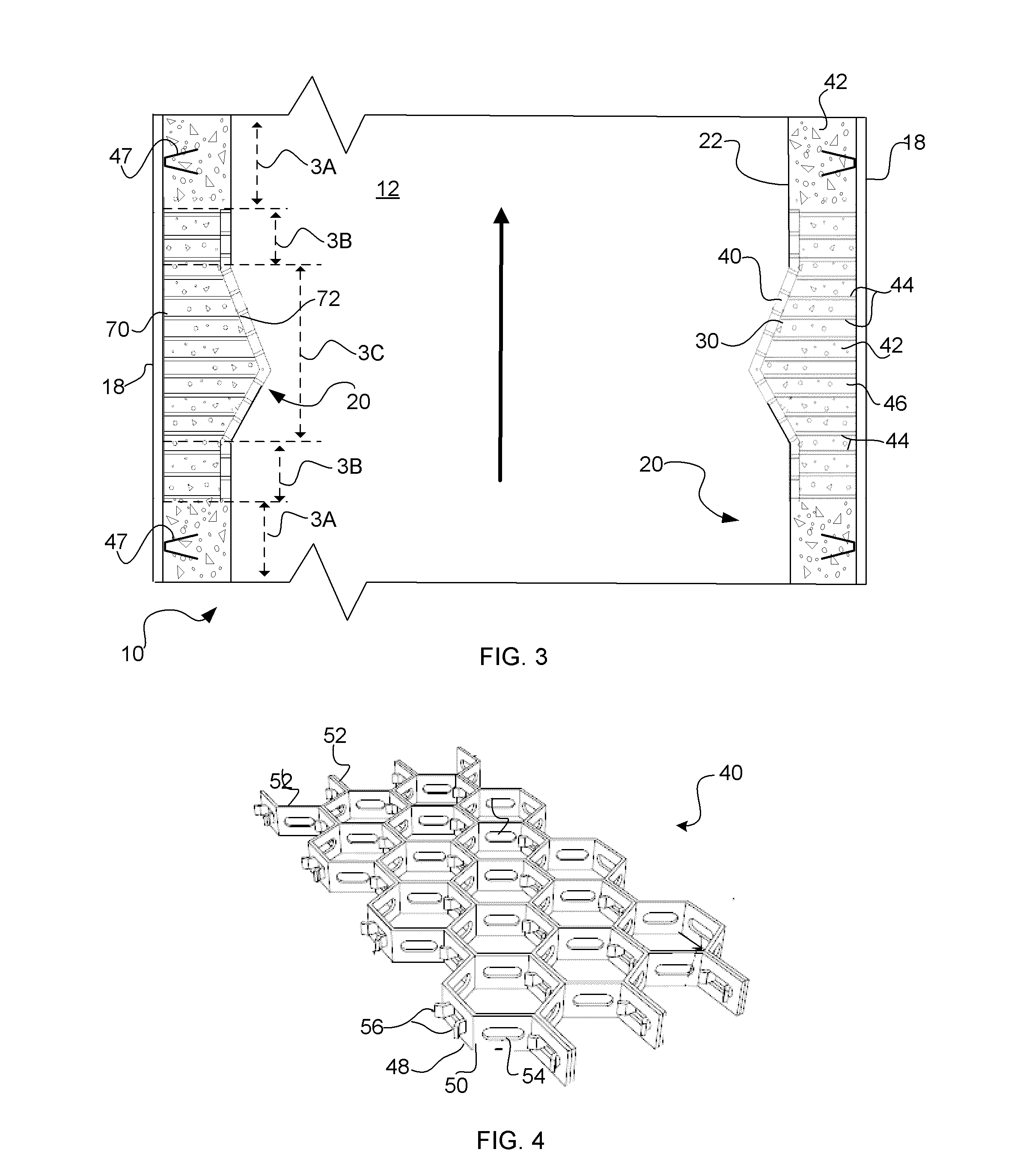
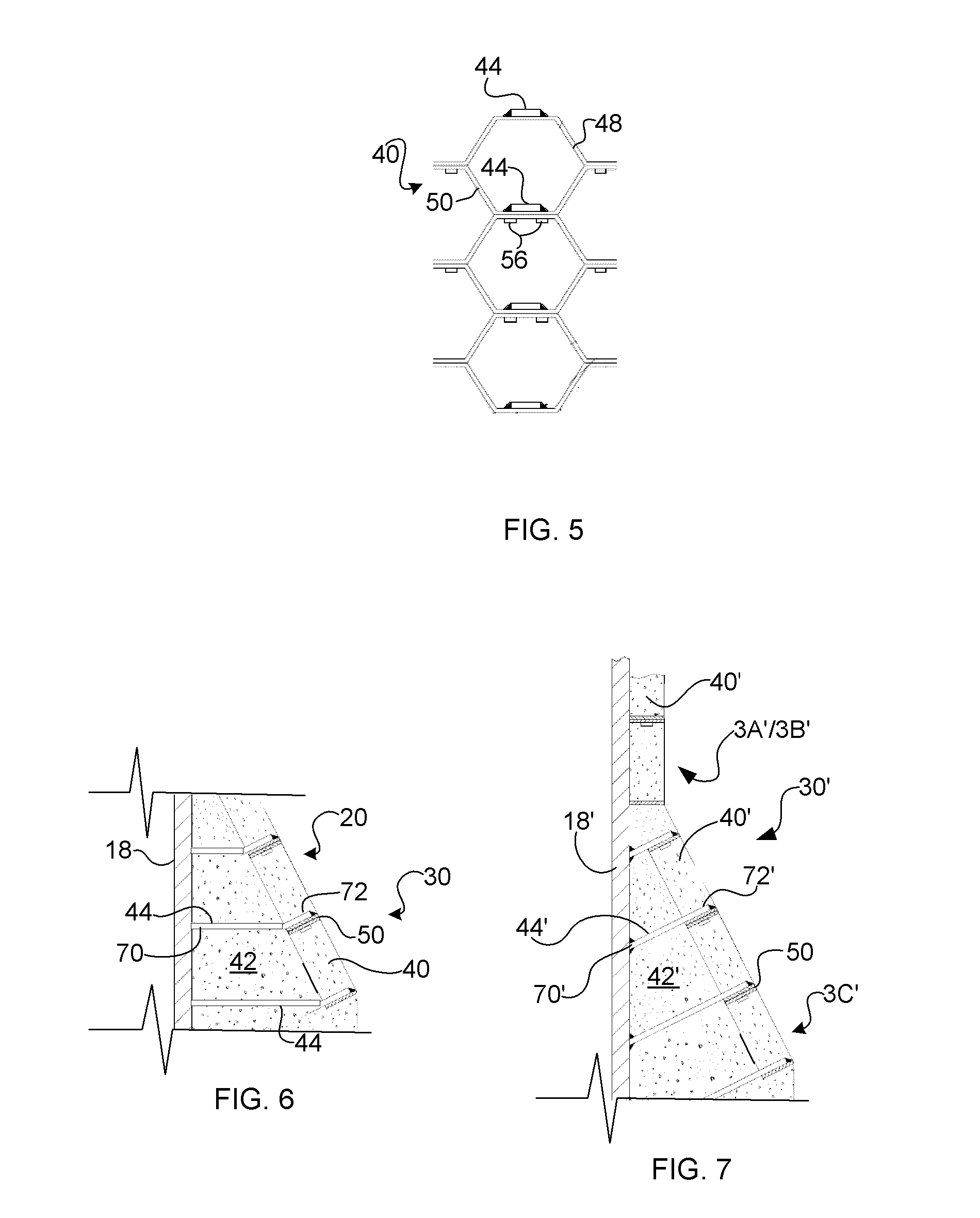
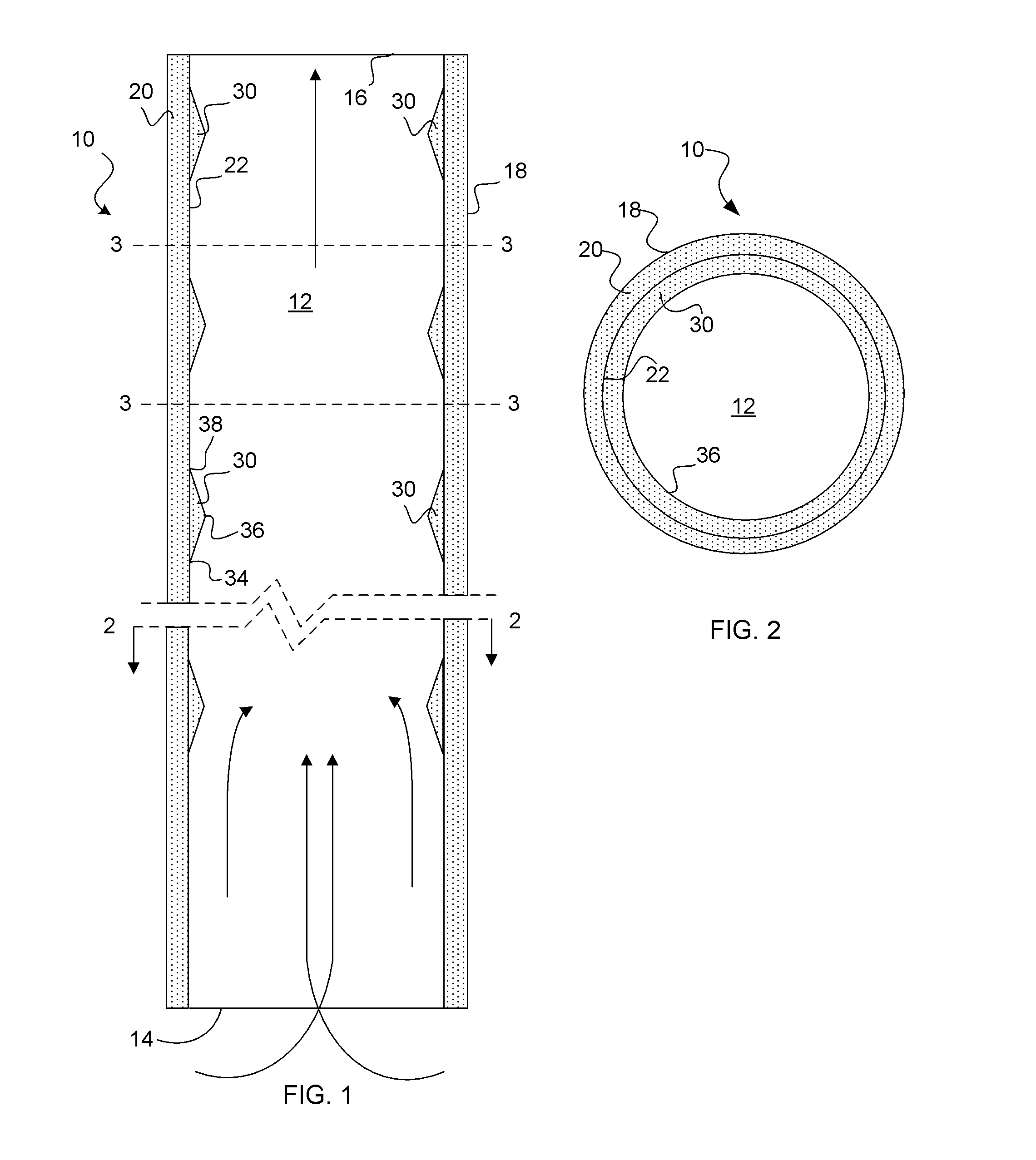
[0015]FIG. 1 schematically illustrates a cross section of an example riser reactor 10 of the invention, while FIG. 2 is an overhead plan view of the same reactor 10 viewed from the perspective of the line 2-2 in the direction indicated by the arrows. The reactor 10 has been illustrated schematically for purposes of clarity and brevity, with elements not important to consideration of the present invention not included. The reactor 10 may be, for example, a catalytic cracking reactor used to convert relative...


PUM


Abstract

An embodiment of the invention includes a riser reactor for reacting a feedstock and catalyst. The riser reactor wall defines an interior. A continuous refractory lining is attached to the reactor wall and defines a plurality of flow disruptors that extend inward from the wall into the reactor interior and disrupt flow patterns of the feedstock and catalyst.

Description

FIELD OF THE INVENTION[0001]A field of the invention is catalytic cracker riser reactors. Another field is catalytic cracker riser reactors having flow disruptors.BACKGROUND OF THE INVENTION[0002]The fluid catalytic cracking (FCC) process is well known for conversion of relatively high-boiling hydrocarbons to lighter hydrocarbons. In many catalytic cracking reactors, often referred to as riser reactors, risers or pipe reactors, a long chain hydrocarbon feed reacts with a catalyst to produce shorter chain products. This can be referred to as cracking the feed. The feed and fluidized catalyst are introduced at a lower entrance to the vertical riser, and travel vertically upwards within the riser reacting at very high temperatures until they reach an upper exit. The riser is often internally lined to minimize heat loss and resist erosion / corrosion.[0003]Reaction efficiency in the riser depends, among other factors, on good and uniform mixing between the feedstock and fluidized catalyst...

Claims


Application Information

Patent Timeline
IPC IPC(8): B01J19/00
CPCC10G11/18B01J8/1845B01J2219/024B01J19/02B01J2208/00938B01J8/34B01J8/1872F27D1/10F27D1/14F27D1/141F27D1/1626F27D2001/1631
Inventor SANDACZ, MICHAEL S.
Owner UOP LLC
Why Eureka
Try Eureka