Hermetic Sealing of Glass Plates

a technology of glass plate and seal, which is applied in the direction of solid-state devices, semiconductor/solid-state device details, coatings, etc., can solve the problems of reducing the efficiency of seal, and reducing the strength of seal, so as to simplify the manufacture of hermetic seals

Active Publication Date: 2013-05-09
FERRO CORP
View PDF0 Cites 63 Cited by
  • Summary
  • Abstract
  • Description
  • Claims
  • Application Information

AI Technical Summary

Benefits of technology

The present invention provides materials, methods, and designs for making hermetic seals to protect electronic circuits and conductive feedthroughs. This simplifies the process of manufacturing these seals, which can be thick film or thin film traces, conductive electrode coatings on glass, ribbon materials, or wires.

Problems solved by technology

The technical problem addressed in this patent text is the conventional laser sealing process which involves heating a large mass of material using an IR laser and absorbing the heat at the interface between the glass plate and the seal material. This process can be time-consuming, lead to contamination, and result in weak seals due to cracking and dimensional changes. The patent aims to improve selective sealing processes, specifically laser sealing, by addressing these issues.

Method used


Image

  • Hermetic Sealing of Glass Plates
  • Hermetic Sealing of Glass Plates
  • Hermetic Sealing of Glass Plates

Examples


example

(D)

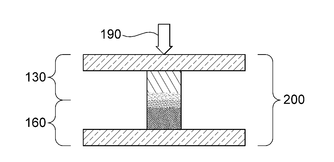
[0107]Single enamel laser seal with medium-temperature glass, Trial TC2141-49A23. The top substrate was a blank glass substrate with no enamel. The bottom substrate had paste 10 syringe deposited in a 2″ square frame pattern, the paste comprising of heavily Mn-doped ZnBi borate glass and modifiers. It was preglazed fired at 470° C., and then lightly sanded to provide a flat top over >50% of the width, yielding an opaque 2.5 mm wide seal, height 180 microns. The two substrates were clamped enamel-to-substrate and laser sealed (950 W, speed=240 inches / minute). The result was a strong seal. It passed initial dye-leak hermeticity tests and microscopy showed the bond area to be without fractures except at corners that got double lased.

Example (E1)

[0108]Formation of enameled coupon with conductive feed-throughs, Trial TC2141-32A1. Paste 10 was screen printed in a 4-square pattern, and then dried at 150° C., the paste comprising a heavily Mn-doped ZnBi borate glass. Ag paste 26060M (Fer...


PUM

PropertyMeasurementUnit
Fractionaaaaaaaaaa
Fractionaaaaaaaaaa
Timeaaaaaaaaaa

Abstract

Durable hermetic seals between two inorganic substrates are produced using a high-intensity electromagnetic energy source, such as laser, to heat and seal enamel layers with controlled absorption of high-intensity energy source. Durable hermetic seals incorporating electrical feedthroughs are also produced.

Description


Claims


Application Information

Patent Timeline
Owner FERRO CORP
Why Eureka
Try Eureka