Structure for placing electronic device

a technology for placing electronic devices and structures, applied in the direction of shaving accessories, machine supports, other domestic objects, etc., can solve the problem that the above-mentioned device may not have enough carrying convenience, and achieve the effect of increasing practicality and reducing the carrying volum

Inactive Publication Date: 2013-05-09
TENNRICH INT
View PDF29 Cites 20 Cited by
  • Summary
  • Abstract
  • Description
  • Claims
  • Application Information

AI Technical Summary

Benefits of technology

[0010]The sucking component of the invention is mobility. The sucking component can be fastened to the through hole at the specific position based upon demands. Further, at least an electronic device is combined with a power bank, and an electrical connection is formed. Alternatively, at least an expansion module is combined with the electronic device, and the electrical connection is formed to reduce the carry volume and increase the practicality. The through hole that is not disposed with the sucking component can also be taken as the function of heat dissipation.

Problems solved by technology

The foregoing device may not have enough carry convenience.

Method used


Image

  • Structure for placing electronic device
  • Structure for placing electronic device
  • Structure for placing electronic device

Examples


Embodiment Construction

[0018]The technical content of the present invention will become apparent by the detailed description of the following embodiments and the illustration of related drawings as follows.

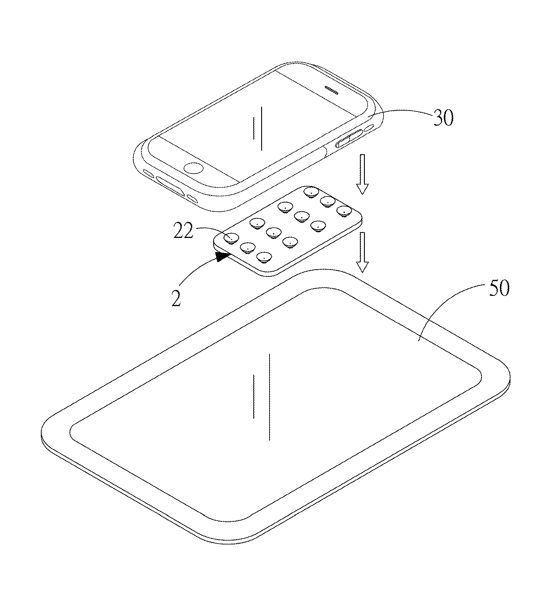
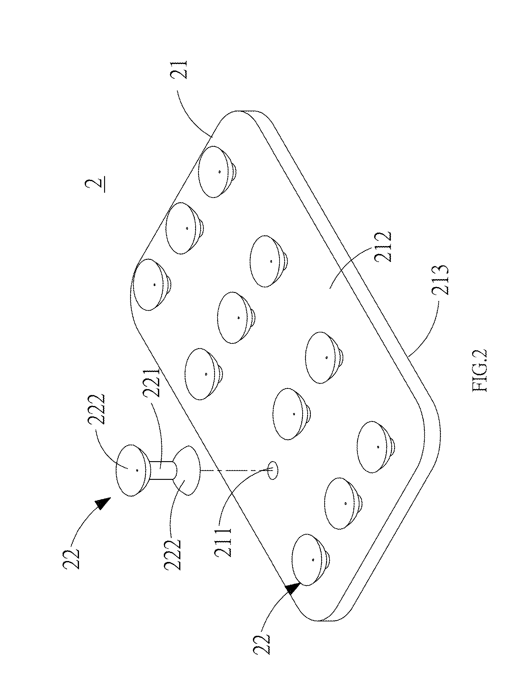
[0019]The improved structure for placing electronic device of the invention is shown in FIG. 2 and FIG. 3. The placing structure 2 is disposed with a main body 21 made of a flexible material and at least one sucking component 22. The flexible material can be rubber, polyurethane (PU), acrylic series or modified elastomer materials. The main body 21 is disposed with at least one through hole 211. The through hole 211 can penetrate through two corresponding surfaces 212, 213 of the main body 21. The sucking component 22 is disposed with a fastening portion 221 and sucking portions 222 extended from two sides of the fastening portion 221. The sucking component 22 is fastened in the through hole 211 through the fastening portion 221. The sucking portions 222 at two sides respectively appear the two correspo...


PUM


Abstract

A placing structure is disposed with a main body made of a flexible material and at least one sucking component. The main body is disposed with at least one through hole. Each sucking component can selectively pass through the through hole to fasten on the main body. At least one electronic device can be combined with a power bank through the sucking component, and the electrical connection is formed. Alternatively, at least one expansion module is combined with the electronic device, and the electrical connection is formed to reduce carry volume and increase practicality.

Description

BACKGROUND OF THE INVENTION[0001]1. Field of the Invention[0002]The invention related to an improved placing structure, and more particularly to an improved placing structure applied in charging electronic device or expanding function and having the efficacy of convenient carrying.[0003]2. Description of the Related Art[0004]The development of electrical technology widely applies consumer electronic products in people daily life at very high speed. For example, small sized electronic products, such as mobile phones, digital cameras, PDAs, laptop computers or MP3 Walkman and the like, must be made to achieve slim and light weight but also must achieve portable by carrying batteries. Moreover, to satisfy the requirement of environmental protection, foregoing products have been equipped with chargeable batteries. These chargeable batteries normally include Nickel-cadmium batteries, Nickel-hydrogen batteries and lithium batteries. The chargeable batteries usually need a charging device ...

Claims


Application Information

Patent Timeline
Patent Type & Authority Applications(United States)
IPC IPC(8): F16B47/00
CPCF16B47/00
Inventor CHEN, SHIH-HUILIN, CHIN-TIENCHENG, HUA-CHI
Owner TENNRICH INT
Why Eureka
Try Eureka