Radar device

a technology of a radar and a detection device, which is applied in the direction of measurement devices, instruments, and using reradiation, etc., can solve the problems of low accuracy of target detection, difficult detection of a distant place, and deterioration of estimation accuracy, so as to suppress the influence of measurement time or measurement distance rang

Active Publication Date: 2013-05-09
PANASONIC INTELLECTUAL PROPERTY MANAGEMENT CO LTD
View PDF2 Cites 71 Cited by
  • Summary
  • Abstract
  • Description
  • Claims
  • Application Information

AI Technical Summary

Benefits of technology

[0032]According to the radar device according to the invention, deterioration of accuracy in estimation of an arrival angle of a target in such a correction manner that a phase shift quantity of a phase component in a correlation value between a reception signal received by each of reception antennas and a transmission signal is calculated properly while influence on a measurement time or measurement distance range is suppressed.

Problems solved by technology

Generally, in a radar device, long-wavelength radio waves are so low in attenuation as to make detection of a distant place possible but are so low in resolution as to make accuracy of target detection low.
On the contrary, short-wavelength radio waves are so high in attenuation as to make detection of a distant place difficult because of easy absorption or reflection by water vapor, cloud, rain, etc. contained in air but are so high in resolution as to make accuracy of target detection high.
For example, when a target moving at a high speed is to be detected, it is therefore difficult to detect the target while following the movement of the target because of the necessity of a lot of scans in accordance with required high-resolution measurement.
In Non-Patent literature 2, because a plurality of antennas are however used so that an RF (Radio Frequency) generator for amplifying a signal received by each antenna and down-converting the frequency of the signal to generate a baseband signal and a signal processor for applying A / D (Analog Digital) conversion to the generated baseband signal to calculate a desired arrival angle are provided in accordance with each antenna, the overall configuration of the receiver is complicated and a cost increase is brought.
However, in Patent Literature 1, to correct a phase shift quantity generated by temporal change of operation in each of the transmitter and the receiver is unconsidered.
For this reason, when a phase shift quantity varying temporally is generated in each sequentially selected antenna and mixed with the signal received by the antenna, accuracy of phase detection according to each antenna deteriorates so that accuracy of target measurement deteriorates.
As a result, the process applied to the switch is complicated so that the overall configuration of the device is complicated.

Method used


Image

  • Radar device
  • Radar device
  • Radar device

Examples


first embodiment

Modification 4 of First Embodiment

[0139]In the first embodiment, it is possible to correct the phase shift quantity in the reception signal due to operation of each element after the signal combiner 13 of the radar receiver 3. When there is fixed phase error in each system from the reception antenna to the switch 11 which are respective elements before the signal combiner 13, it is however difficult to correct the phase shift quantity inclusive of the fixed phase error.

[0140]In Modification 4 of the first embodiment, fixed phase error E(s) in each system from the reception antenna to the switch 11 is measured in advance so that the measured phase error E(s) is held in the signal processor.

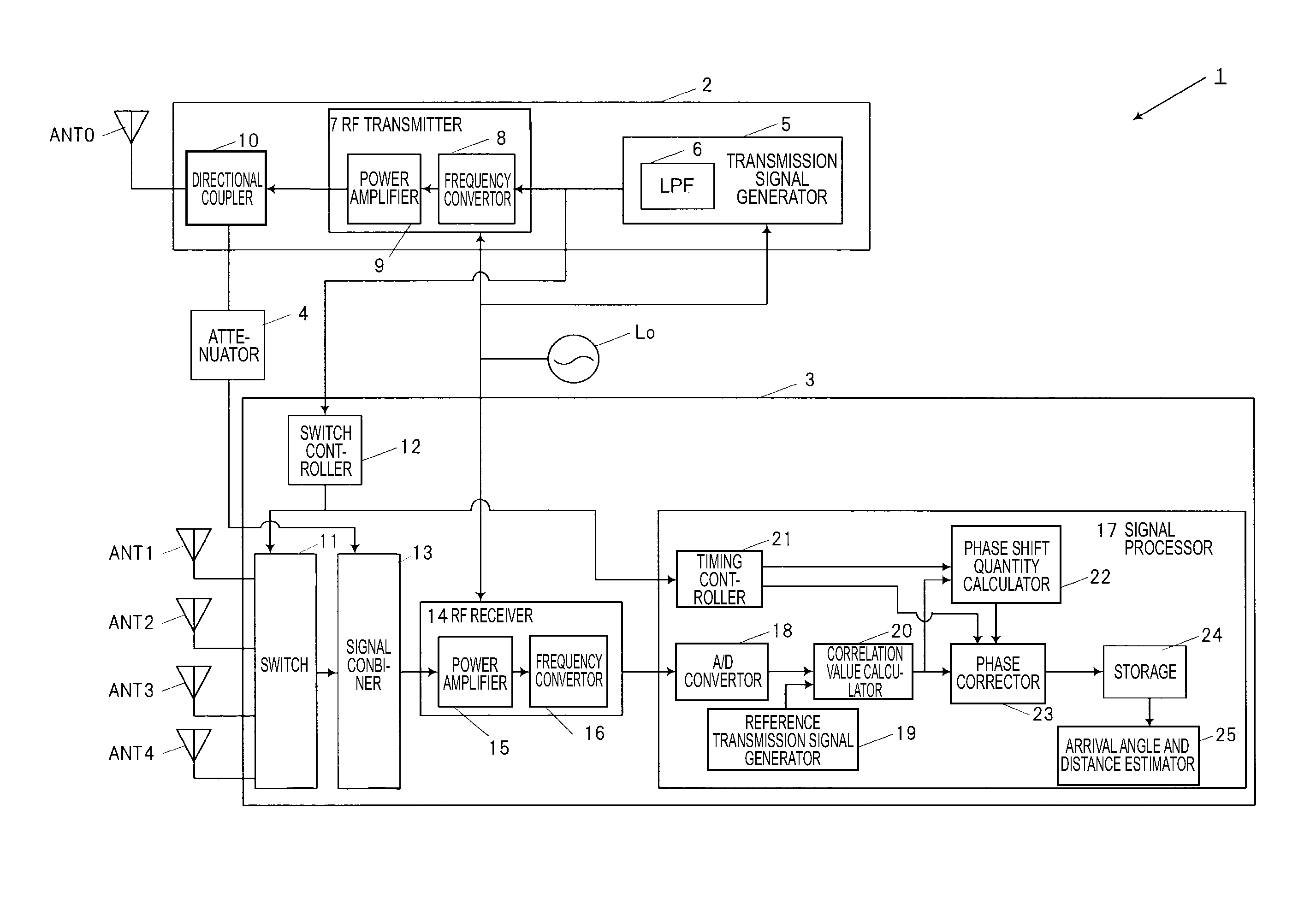
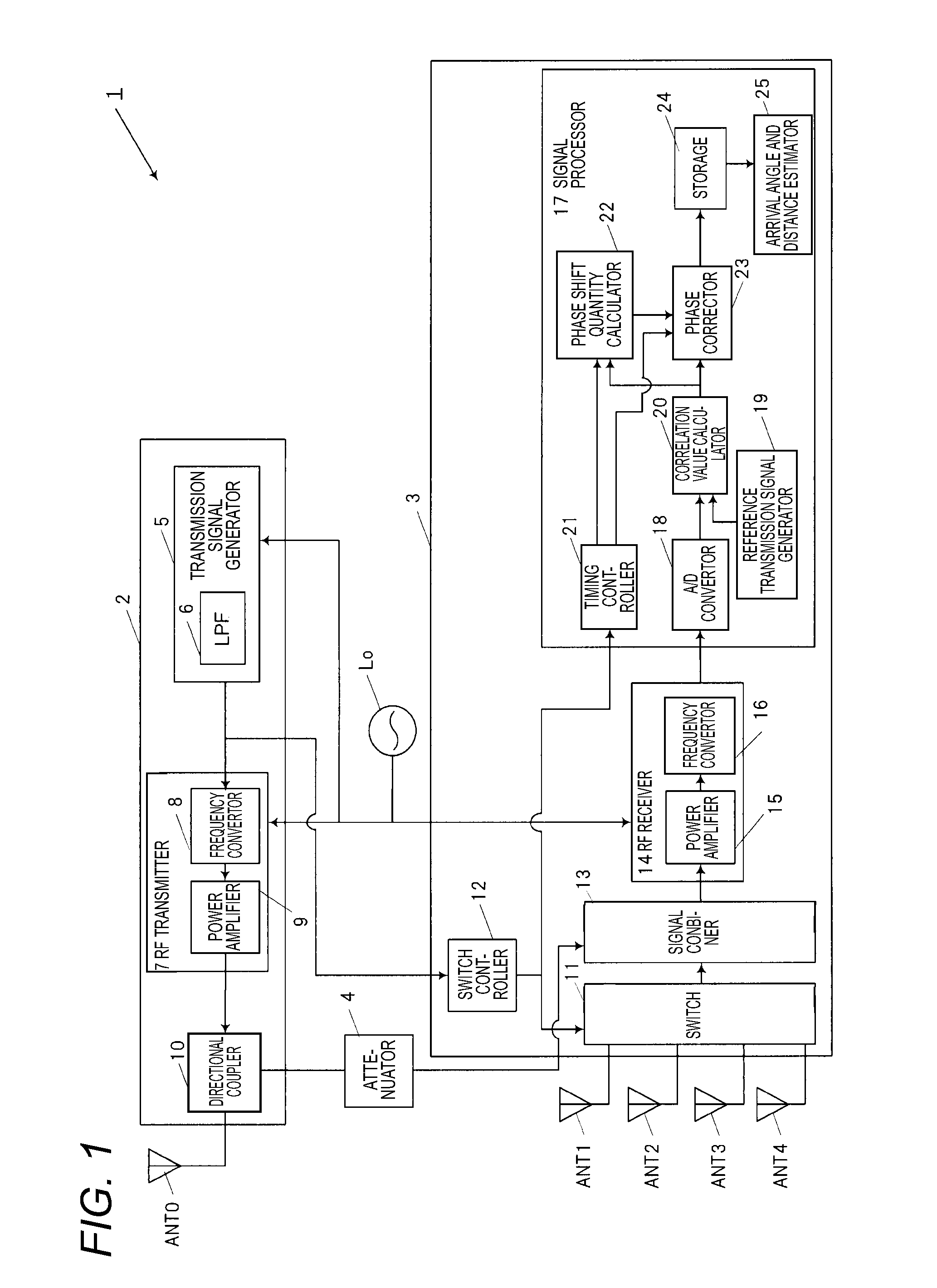
[0141]The signal processor 17d has an A / D converter 18, a reference transmission signal generator 19, a correlation value calculator 20, a timing controller 21, a phase shift quantity calculator 22, an intersystem fixed phase error storage 30, a phase corrector 23, a storage 24, and an arrival angl...

second embodiment

[0145]In a second embodiment, a transmission antenna ANT0 and reception antennas ANT1 to ANT4 are disposed so as to be located so that a high-frequency transmission signal transmitted from the transmission antenna ANT0 can be directly received by each of the reception antennas ANT1 to ANT4 by using side lobes of the directional pattern of the transmission antenna ANT0, side lobes of the reception antennas ANT1 to ANT4 or the like. Moreover, in the second embodiment, the two measurement periods of a reference phase update period and an ordinary period are repeated at regular intervals so that calculation of the phase shift quantity in each reception antenna ANTs and correction of the phase component of the correlation value based on the calculated phase shift quantity are performed.

[0146]In the reference phase update period, the second switch 31 is turned on to perform inputting of the high-frequency transmission signal attenuated by the attenuator 4 to the signal combiner 13 in the ...

third embodiment

[0211]The configuration and operation of a radar device 1f according to a third embodiment will be described with reference to FIGS. 11 and 12. FIG. 11 is a block diagram illustrating the internal configuration of the radar device 1f according to the third embodiment.

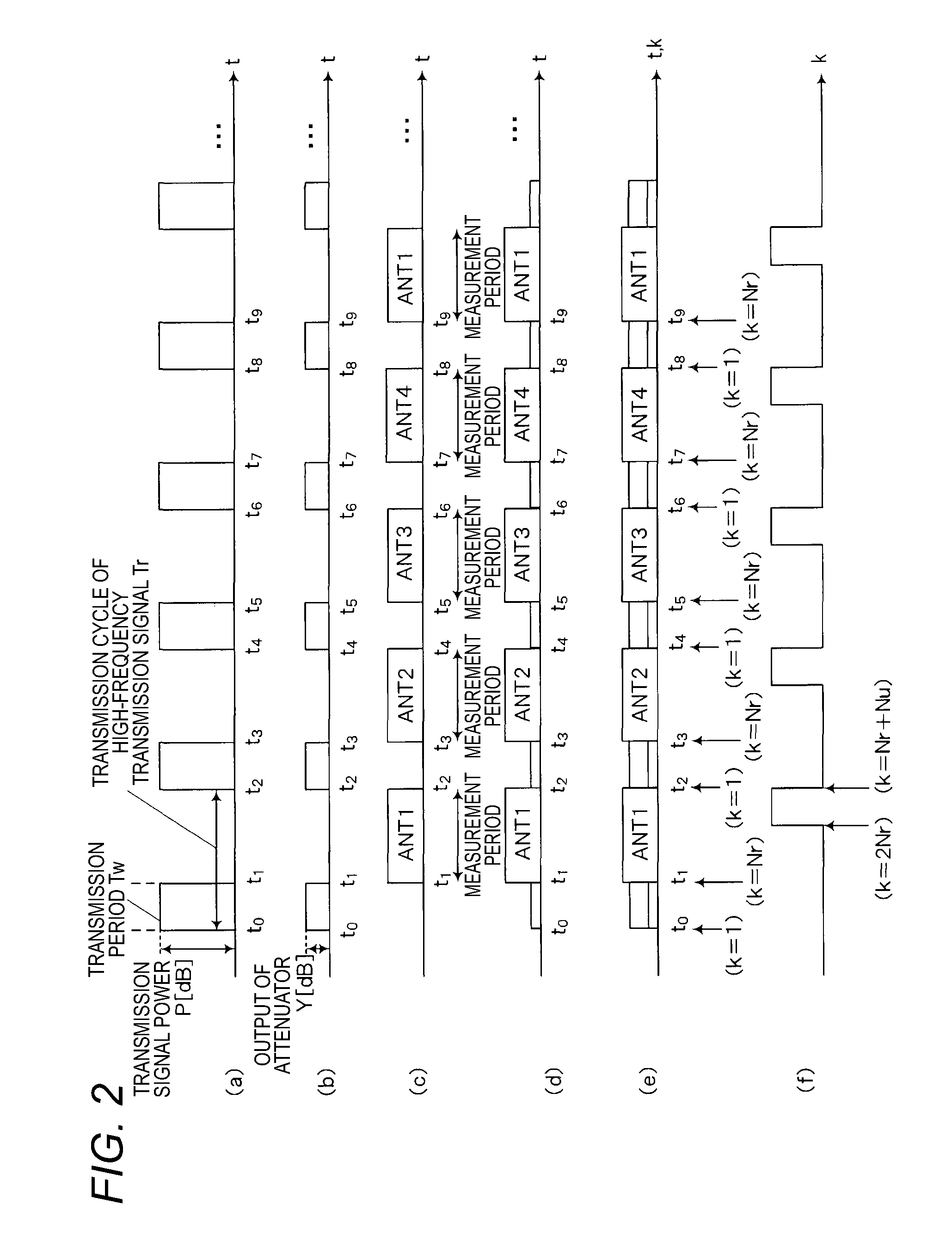
[0212]FIG. 12 is a timing chart concerned with operation of the radar device 1f according to the third embodiment. In FIG. 12, (a) is an explanatory view illustrating a timing chart of a high-frequency transmission signal. In FIG. 12, (b) is an explanatory view illustrating a timing chart of the high-frequency transmission signal input to a signal combiner 13f from an attenuator 4. In FIG. 12, (c) is an explanatory view illustrating a period of measurement by each of reception antennas ANT1 to ANT4. In FIG. 9, (d) is an explanatory view illustrating a reception signal output from the signal combiner 13f and a period of measurement by each of the reception antennas ANT1 to ANT4.

[0213]In FIG. 12, (e) is an explanatory vie...


PUM


Abstract

The disclosed technique includes transmitting a signal intermittently according to a transmission cycle having a predetermined transmission period and a non-transmission period; receiving the signal reflected from a target with reception antennas; and detecting the target from the reflected signal. A high-frequency transmission signal attenuated during the transmission period and a receipt signal received during the non-transmission period are combined together. A correlation value between a reference transmission signal and the receipt signal in the combined signal is calculated, and the amount of phase shift in an arbitrarily selected reception antenna is calculated from the correlation value of a reference reception antenna, and the correlation values of the other reception antennas. The phase component of the correlation value of the arbitrarily selected reception antenna is corrected on the basis of the amount of phase shift.

Description

TECHNICAL FIELD[0001]The present invention relates to a radar device which sequentially receives a signal obtained due to reflection by a target, by a plurality of antennas.BACKGROUND ART[0002]A radar device radiates radio waves from a point of measurement to space and receives a signal reflected from a target to thereby measure a distance, a direction, etc. from the point of measurement to the target. Development of a radar device capable of detecting not only a car but also a pedestrian or the like as a target by high-resolution measurement using short-wavelength radio waves such as microwaves or millimeter waves has advanced in recent years.[0003]Generally, in a radar device, long-wavelength radio waves are so low in attenuation as to make detection of a distant place possible but are so low in resolution as to make accuracy of target detection low. On the contrary, short-wavelength radio waves are so high in attenuation as to make detection of a distant place difficult because o...

Claims


Application Information

Patent Timeline
Patent Type & Authority Applications(United States)
IPC IPC(8): G01S7/35G01S13/931
CPCG01S7/285G01S13/931G01S13/42G01S7/4021G01S7/35
Inventor KISHIGAMI, TAKAAKIMUKAI, HIROHITONAKAGAWA, YOICHI
Owner PANASONIC INTELLECTUAL PROPERTY MANAGEMENT CO LTD
Why Eureka
Try Eureka