

Image display device
- Summary
- Abstract
- Description
- Claims
- Application Information
AI Technical Summary
Benefits of technology
Problems solved by technology
Method used
Image

Examples
first embodiment
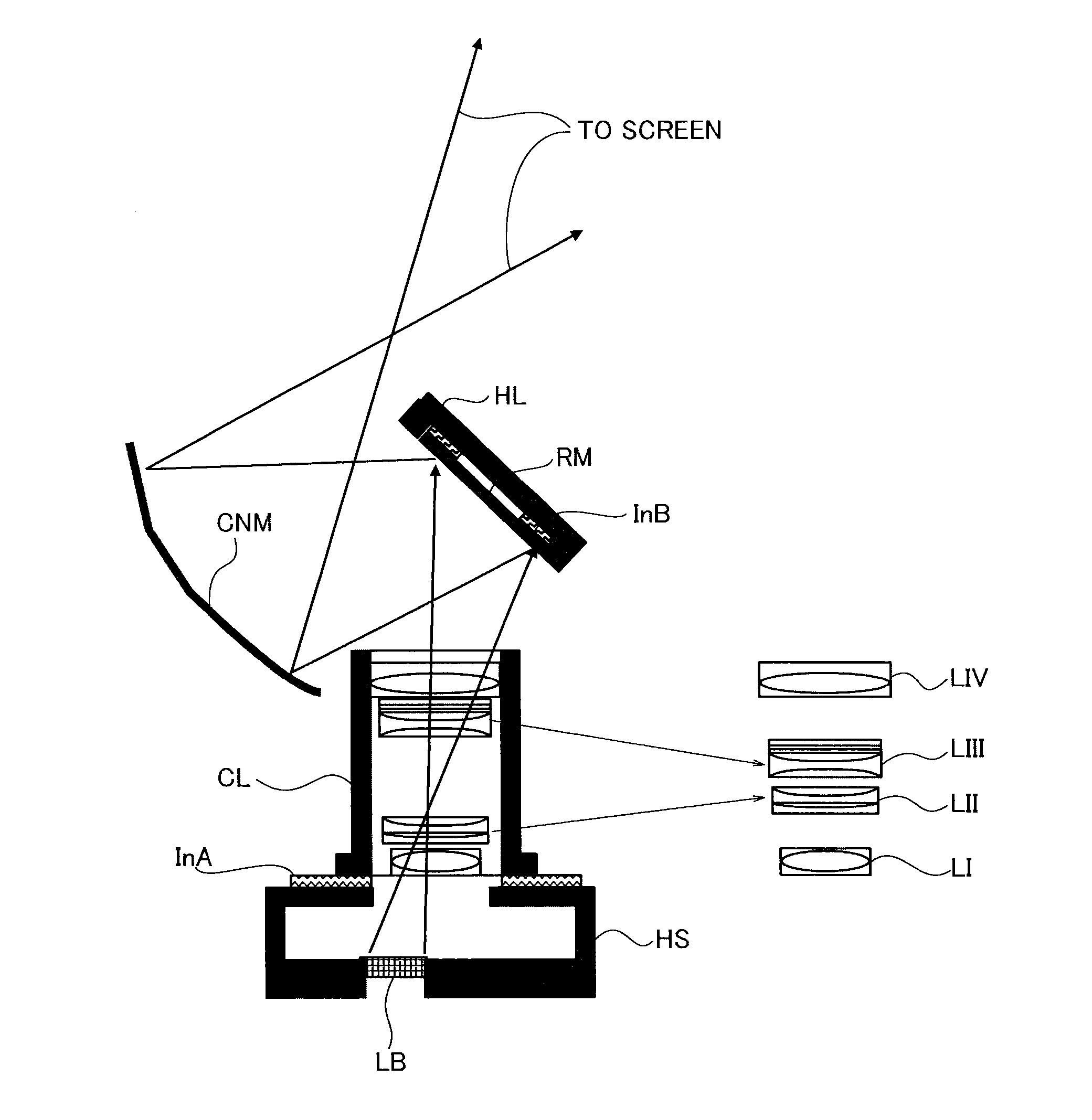
[0062]FIG. 8 shows the essential part of an image display device according to a first embodiment. The image display device comprises an illumination system, a projector system including a refractive optical system, a light source and a light bulb LB. The light bulb LB is a digital micro mirror device (DMD) and held in a housing HS. A lens barrel CL is connected with the housing HS via a first intervenient element InA. The refractive optical system is contained in the lens barrel CL and it comprises first to fourth lens groups LI, LII, LIII, LIV arranged in this order from the light bulb side.
[0063]The image display device also comprises a reflecting mirror RM held in a holder HL via a second intervenient element InB, and a concave mirror CNM as a mirror train.
[0064]A light beam from the light source illuminates the display surface of the light bulb LB via the illumination system, and is reflected thereby, changed in intensity by an image displayed on the surface and incident on the ...
second embodiment
[0081]Now, an image display device according to a second embodiment is described with reference to FIG. 9. The second embodiment differs from the first embodiment in that a screw structure BS is provided to adjust the distance between the light bulb LB and first lens group LI in replace of the first intervenient element InA.
[0082]The screw structure BS adjusts the distance between the light bulb LB and first lens group LI. It constitutes the second focus structure together with the second intervenient element InB, so that the distance is adjusted with the screw structure in the assembly process of the optical systems and the screw structure BS is secured after the adjustment, so as not to allow a user to adjust it.
[0083]Note that the second focus structure should not be limited to the first and second intervenient elements InA, InB and the screw structure BS. Any structure can be arbitrarily used as long as it can achieve the same functions.
third embodiment
[0084]An image display device according to a third embodiment is described with reference to FIG. 10. In the present embodiment the refractive optical system is comprised of the first to fourth lens groups LI to LIV.
[0085]In the present embodiment the focus adjustment of a projected image is done by floating focusing in which the second and third lens groups LII, LIII are moved. The fourth lens group LIV is fixed. That is, the second and third lens groups LII, LIII and a moving mechanism therefor constitute the first focus structure.
[0086]Meanwhile, the second focus structure is comprised of the fourth lens group LIV and a structure to move it along the optical axis.
[0087]Moving the fourth lens group LIV along the optical axis can attain the same focusing effects as those by the protrusion of the entire lens barrel in the first and second embodiments. The fourth lens group LIV is moved by a cam structure different from the one for the second and third lens groups LII, LIII in the as...
PUM
 Abstract
Description
Claims
Application Information