Localised energy concentration

Active Publication Date: 2013-05-09
OXFORD UNIV INNOVATION LTD
View PDF3 Cites 10 Cited by
  • Summary
  • Abstract
  • Description
  • Claims
  • Application Information

AI Technical Summary

Benefits of technology

[0052]The gas pocket itself must be formed in some manner. In a particular set of embodiments it is nucleated using a system similar to that described in U.S. Pat. No. 7,445,319, where a laser is used in conjunction with nano-particles in the liquid to nucleate a bubble. In a different set of embodiments a bubble could be nucleated using an unstable emulsion of different liquids. In another set the bubble is nucleated using an appropriately targeted pressure wave designed to induce cavitation in the liquid. In the set of embodiments where the gas pocket is attached to the wall, a specifically controlled volume of gas could be pumped in through a passage in the target surface in order to expand a bubble on the surface. This set of embodiments has the advantage of great control over the contents and size of the gas pocket generated. In the set of embodiments where the liquid medium is a gel the gas pocket can be pre-manufactured by punching or otherwise cutting out or molding the correct shape from the gel block to be used.
[0053]In another set of embodiments the gas pocket is formed with the use of a pre-manufactured membrane that defines the boundary between the gas pocket and the medium and hence also defines the gas pocket's shape. The use of a thin membrane in this manner allows a decoupling of the liquid and gas materials, allowing any choice of combination of compositions to be made. It also allo

Problems solved by technology

This is one of the mechanisms which gives rise to the well-known problem of cavitation damage of surfaces when shockwaves are generated in the presence o

Method used


Image

  • Localised energy concentration
  • Localised energy concentration
  • Localised energy concentration

Examples


first embodiment

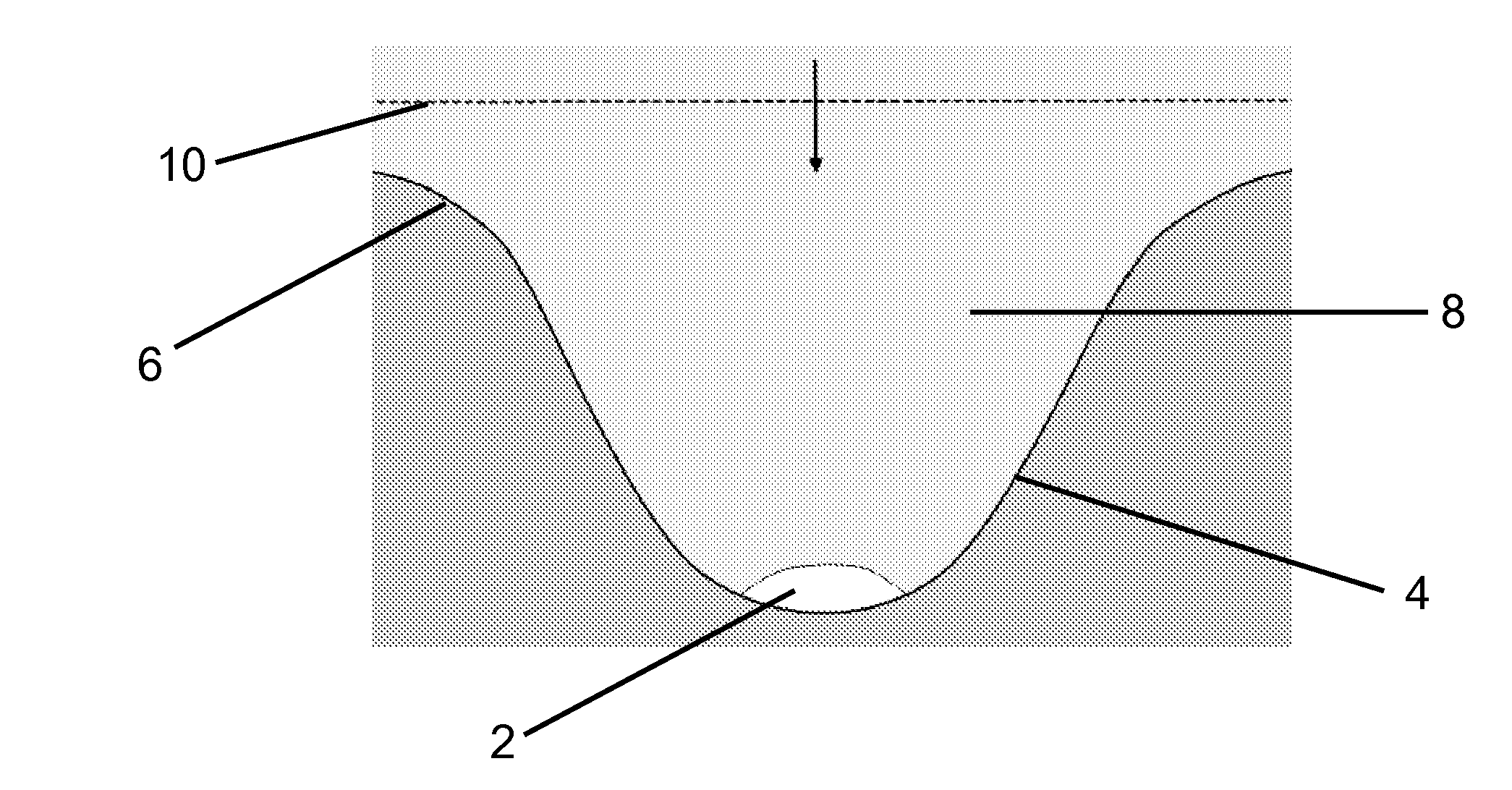
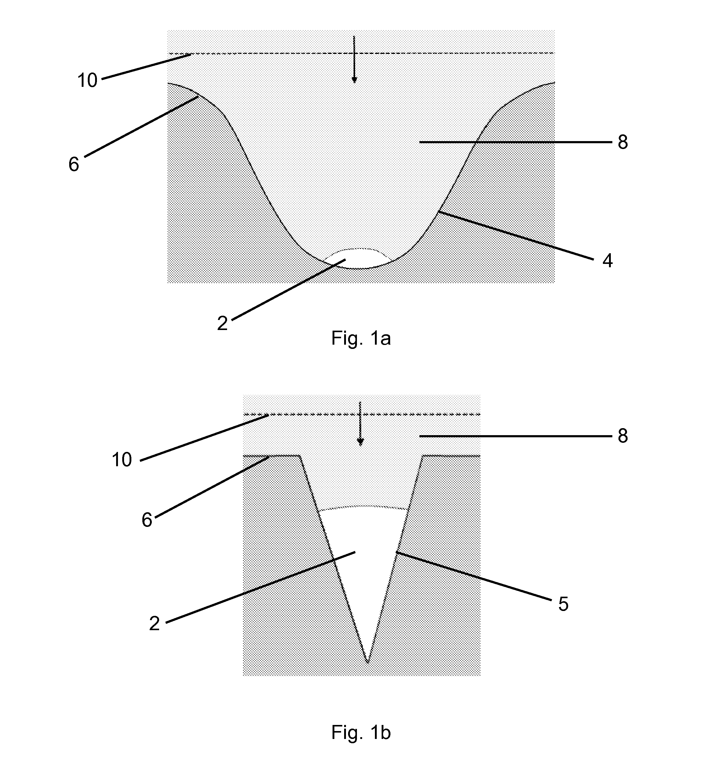
[0064]FIGS. 1a and 1b show schematically arrangements in accordance with two respective embodiments of one aspect of the invention. In each case a solid surface 6, for example made from high strength steel, is placed inside a non-gaseous medium 8 in the form of a hydrogel, for example a mixture of water and gelatine. Defined in the hydrogel medium 8 is a gas pocket 2 filled with vaporous fuel suitable for taking part in a nuclear fusion reaction. In both cases the gas pocket 2 is attached to the target surface 6 inside a concave depression. In the case of the first embodiment in FIG. 1a, the depression 4 is parabolic and relatively large such that only one side of the gas pocket 2 is attached to the surface 6. The size of the apparatus is flexible but a typical dimension of this diagram could be between 0.1 and 1×10⁻⁵ m.

second embodiment

[0065]In the case of the second embodiment in FIG. 1b, the gas pocket 2 is received in a much smaller, V-shaped tapering depression 5 which could be machined or formed as the result of a naturally occurring crack in the surface 6.

[0066]In operation a shockwave 10 is created from an explosion, for instance with a pressure of 5 GPa, within the gel medium 8. This is represented in both FIGS. 1a and 1b as a line propagating in the direction of the arrow towards the pocket of gas 2. First the shockwave 10 strikes the upper parts of the target surface 6, causing the shockwave 10 to change shape as it advances towards the pocket of gas 2. In this manner the shape of the shockwave 10 that advances into the pocket of gas 2 can be explicitly controlled by shaping the surface 6 accordingly. The shaped shockwave 10 will then strike the pocket of gas 2, compressing it against the target surface 6 as the shockwave 10 propagates through the gas pocket 2. Reflections of the shockwave 10 from the su...


PUM


Abstract

A method of producing a localised concentration of energy comprises creating at least one shockwave (10) propagating through a non-gaseous medium (8) so as to be incident upon a pocket of gas (2) within the medium (8). The pocket of gas (2) is attached to a surface (6) comprising a depression (4) shaped so as partially to receive the gas pocket (2). An apparatus for producing a localised concentration of energy comprises a non-gaseous medium (8) having therein a pocket of gas (2). The pocket of gas (2) is attached to a surface (6) comprising a depression (4) shaped so as partially to receive the gas pocket (2). The apparatus further comprises means for creating at least one shockwave (10) propagating through the medium (8) so as to be incident upon the pocket of gas (2).

Description

TECHNICAL FIELD[0001]This invention relates to methods and apparatuses for producing very high localized energies. It relates particularly, although not exclusively, to generating localized energies high enough to cause nuclear fusion.BRIEF DESCRIPTION OF RELATED ART[0002]The development of fusion power has been an area of massive investment of time and money for many years. This investment has been largely centered on developing a large scale fusion reactor, at great cost. However, there are other theories that predict much simpler and cheaper mechanisms for creating fusion. Of interest here is the umbrella concept “inertial confinement fusion”, which uses mechanical forces (such as shock waves) to concentrate and focus energy into very small areas.[0003]Much of the confidence in the potential in alternative methods of inertial confinement fusion comes from observations of a phenomenon called sonoluminescence. This occurs when a liquid containing appropriately sized bubbles is driv...

Claims


Application Information

Patent Timeline
IPC IPC(8): G21B3/00
CPCG21B3/006G21B3/008Y02E30/10G21B3/00B01J19/10G10K15/043
Inventor VENTIKOS, YIANNISHAWKER, NICHOLAS
Owner OXFORD UNIV INNOVATION LTD
Why Eureka
Try Eureka