
Cup feeder

a feeder and cup technology, applied in the field of cups, can solve the problems of high rejection rate, waste, and even slightly different cups, and achieve the effects of low rejection rate, positive control, and reliably handled

Active Publication Date: 2013-05-09
R A JONES
View PDF7 Cites 19 Cited by
  • Summary
  • Abstract
  • Description
  • Claims
  • Application Information

AI Technical Summary

Benefits of technology

The patent is about a system that controls the spacing of cups in a positive way, without the need for timing screws. The guides on the system engage the cups consistently, regardless of their shape, weight, or lid configuration. This means that even when there are different types of cups being processed at high speeds, the system can handle them all without needing new guide placement or adjustment. This results in reliable handling of a wide variety of cup sizes, shapes, weights, and lids, with low levels of rejection.

Problems solved by technology

For example, if a top guide is adjusted down to engage a sunken cup lid, it may not pass cups with bulging top lids and which hangs up or causes voids in the line of feeding cups, resulting in downstream packaging aberrations, waste, etc.
If a handling or guiding system is not “tuned” to a particular cup parameter, cups of even slightly different parameters may upset, fall over or otherwise jam up the feeder once the cups are placed in single file.
This results in a high rate of rejection (or lower rate of operational efficiency).

Method used


Image

  • Cup feeder
  • Cup feeder
  • Cup feeder

Examples


Embodiment Construction

Cup Pitch:

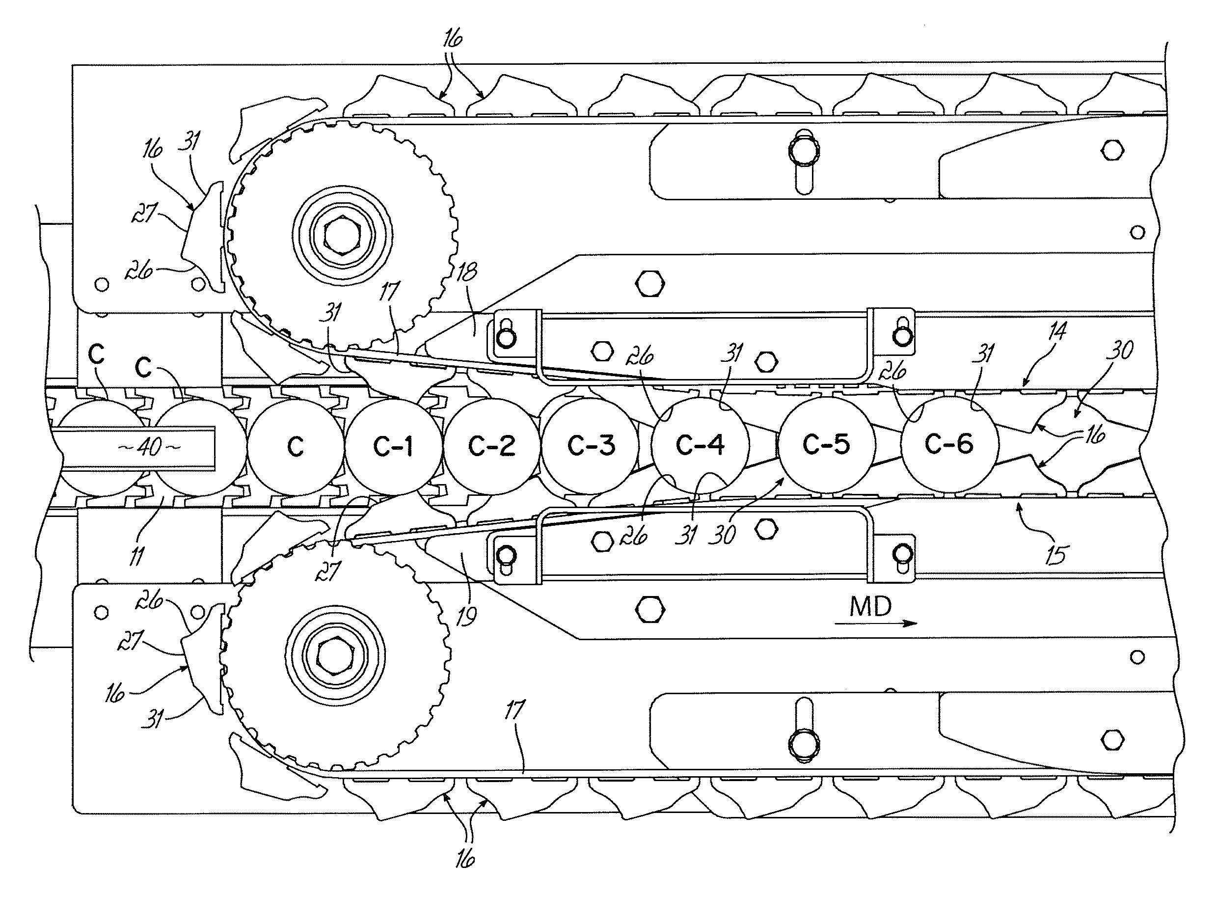
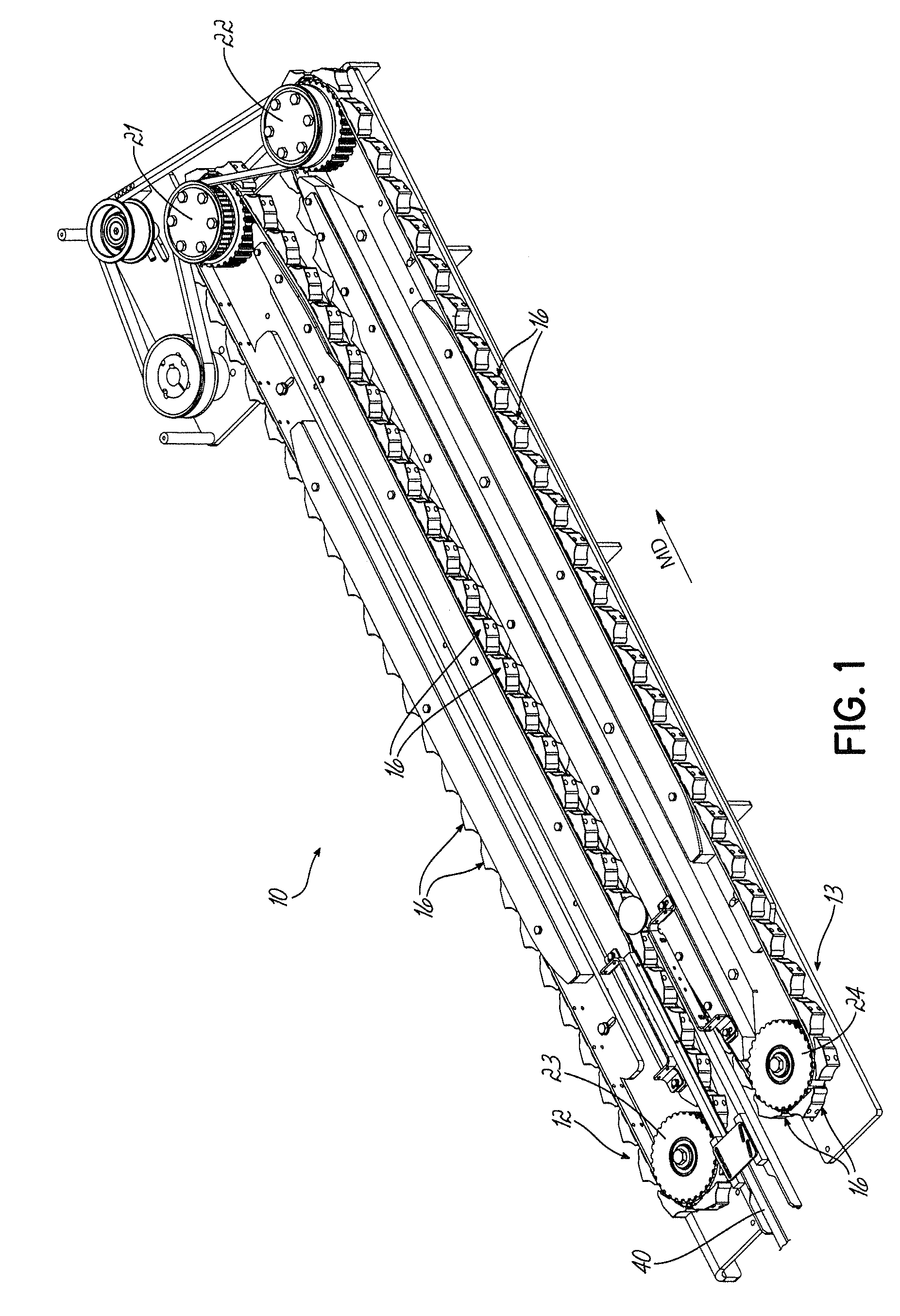
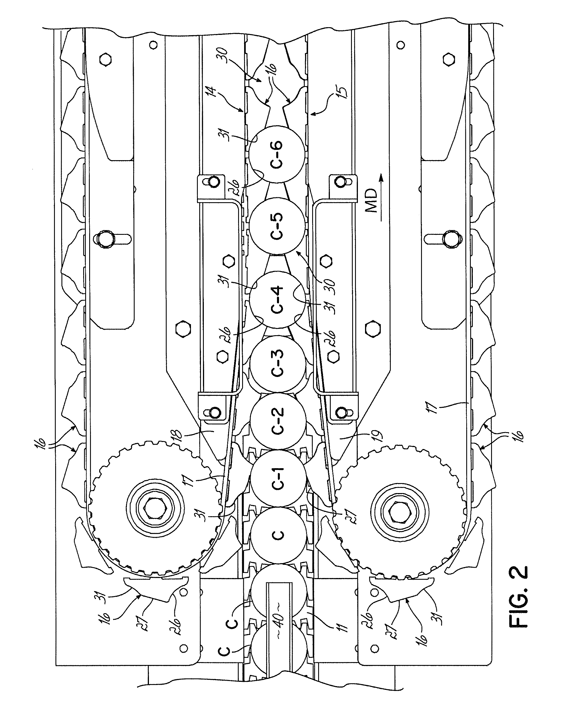
[0044]Turning now to the drawings, FIGS. 1-8 illustrate a preferred embodiment of the cup spacing apparatus of the invention. While the term “cup” is used herein, it will be appreciated the invention relate to the handling of containers which, here, are referred to particularly and preferably as “cups” as described, having rims as shown.

[0045]In FIG. 1, cups (not shown) enter the spacing apparatus 10 from the left end and are conveyed by conveyor 11 between two linear stars, comprising conveyors 12, 13 having opposed, elongated operative runs 14, 15 (FIG. 2) operating in a downstream machine direction MD, transporting cups along a cup path having an elongated center line extending between conveyors 12, 13.

[0046]Conveyors 12, 13 each comprise a series of lugs 16 carried on a flexible member or belt 17 backed up by a respective elongated guide 18, 19, respectively. The opposed runs 14, 15 are inclined toward one another (tapered respectively inward) at the left-hand entry en...


PUM


Abstract

A column of cups guided by their rims in elongated slots is spaced into desired cup pitch by one or more linear stars from which the cups can be transferred for packaging. The linear stars have lugs engaging and spacing the cups. In another aspect of the invention, cups are manipulated into patterns for final grouping and packaging and by a plurality of cup orienting pickers engaging, inverting and re-orienting the cups. In one final packaged cup group of two or more layers, alternating cups in each layer are inverted and a top lid of a cup in an upper layer is disposed on a top lid of a cup in a bottom layer, while a bottom of a cup in an upper layer is disposed on a bottom of a cup in a lower layer, and in an alternating pattern.

Description

RELATED APPLICATION[0001]The application claims priority to U.S. Ser. No. 61 / 628,753 filed Nov. 4, 2011, the disclosure of which is hereby incorporated herein by reference in its entirety.FIELD OF THE INVENTION[0002]This invention relates to cup feeding and more particularly to the transfer of individual cups, such as, for example, single-serve cups used in brewing single cups of coffee, from a randomly-fed orientation, both toward and into cartons for packaging, transport and sale.BACKGROUND OF THE INVENTION[0003]Cups for single serve coffee brewing, for example, are formed, filled and sealed and presented in random volume and mixed orientation from forming and filling machines. Typically, such cups are accumulated in random batches and are fed from a feeder drum or bowl into a lid-up, single file line for packaging.[0004]Such cups may vary, at least slightly in shape, in weight and in overall height, depending on whether the typical foil lid or cover outwardly bulges or is somewha...

Claims


Application Information

Patent Timeline
IPC IPC(8): B65B35/30B65B35/56
CPCB65B35/24B65B35/243B65G47/28B65B35/58B65B35/38B65G2201/0244B65G15/14B65G47/244B65G47/252B65G47/084B65B35/36B65B35/56
Inventor LUKES, MATTHEW R.BRUGGER, JEROME
Owner R A JONES
Learn More