
Electrical steel sheet and method for manufacturing the same

Active Publication Date: 2013-05-09
NIPPON STEEL CORP
View PDF3 Cites 8 Cited by
  • Summary
  • Abstract
  • Description
  • Claims
  • Application Information

AI Technical Summary

Benefits of technology

The present invention provides an insulating film that helps to remove molding resin while maintaining high insulation performance. This results in improved efficiency and efficiency in the manufacturing process.

Problems solved by technology

This is because objects such as the improvement in durability and weather resistance cannot be attained if the molding resin does not closely adhere to the laminated iron core.
Besides, in a motor using a magnet, the magnet is fixed to the motor by using the molding resin, but the fixing of the magnet becomes insufficient if the adhesiveness is low.
On the other hand, it turns out that various problems occur during a manufacturing process of the motor and so on when the adhesiveness between the molding resin and the laminated iron core is too high.
For example, in a motor and so on used for a vehicle, there is a case when a compressive stress acts on the laminated iron core from the molding resin, and iron loss increases.
In other words, if the molding resin and an exposed part of the laminated iron core are adhered in a case where the resin molding has been performed after a conductive part such as a coil is attached to the laminated iron core, there is a case where the compressive stress from the molding resin acts on the laminated iron core and performance of the motor is lowered caused by deterioration of the iron loss.
Besides, when the magnet is fixed to the motor with the molding resin, it is difficult to remove the molding resin adhered to unnecessary portions if the adhesiveness between the molding resin and the laminated iron core is too high.

Method used


Image

  • Electrical steel sheet and method for manufacturing the same
  • Electrical steel sheet and method for manufacturing the same

Examples


example

[0106]Next, experiments performed by the present inventors are described. Conditions and so on in these experiments are examples applied to verify execution possibilities and effects of the present invention, and the present invention is not limited to these examples.

[0107]A base iron having a composition for a non-oriented electrical steel sheet containing Si: 2.5%, Al: 0.5%, and Mn: 0.05% each in mass % was produced. The thickness of the base iron was 0.35 mm, and the centerline average roughness (Ra) was 0.46

[0108]Further, various solutions for the first component were prepared. The components of these solutions are presented in Table 1.

TABLE 1PART BYSOLUTION No. FORMETAL PHOSPHATE ORKIND OFMASS OFOTHERFIRST COMPONENTCOLLOIDAL SILICAORGANIC RESINORGANIC RESINADDITIVE1MAGNESIUM PHOSPHATEACRYLIC RESIN 1202ALUMINUM PHOSPHATEACRYLIC RESIN 173MANGANESE PHOSPHATEEPOXY RESIN 1354NICKEL PHOSPHATEACRYLIC RESIN 1155ALUMINUM PHOSPHATE +POLYESTER RESIN15PHOSPHONIC ACID:MAGNESIUM PHOSPHATE0.5...


PUM

PropertyMeasurementUnit
Temperatureaaaaaaaaaa
Lengthaaaaaaaaaa

Abstract

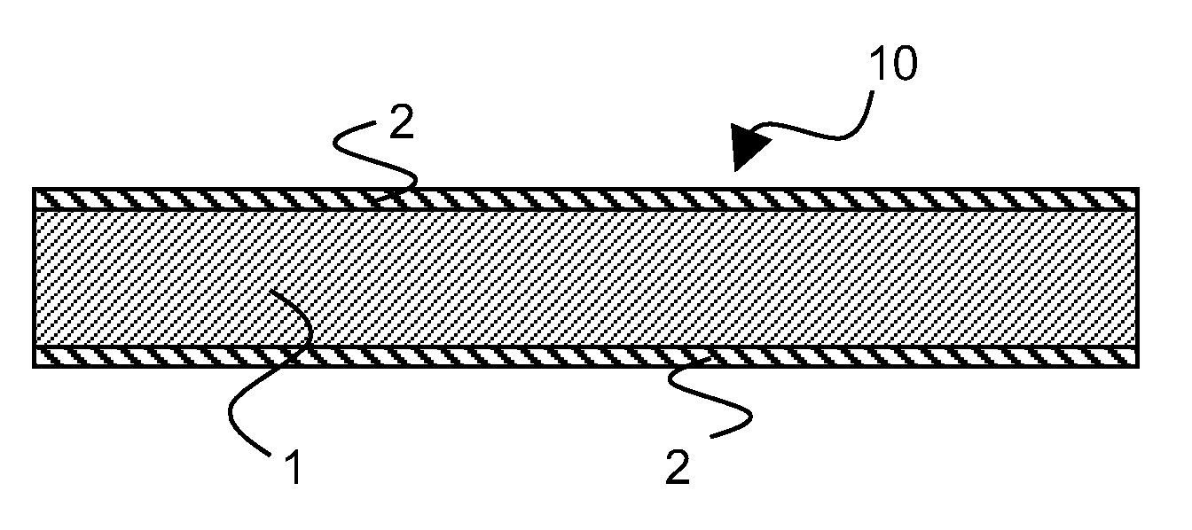
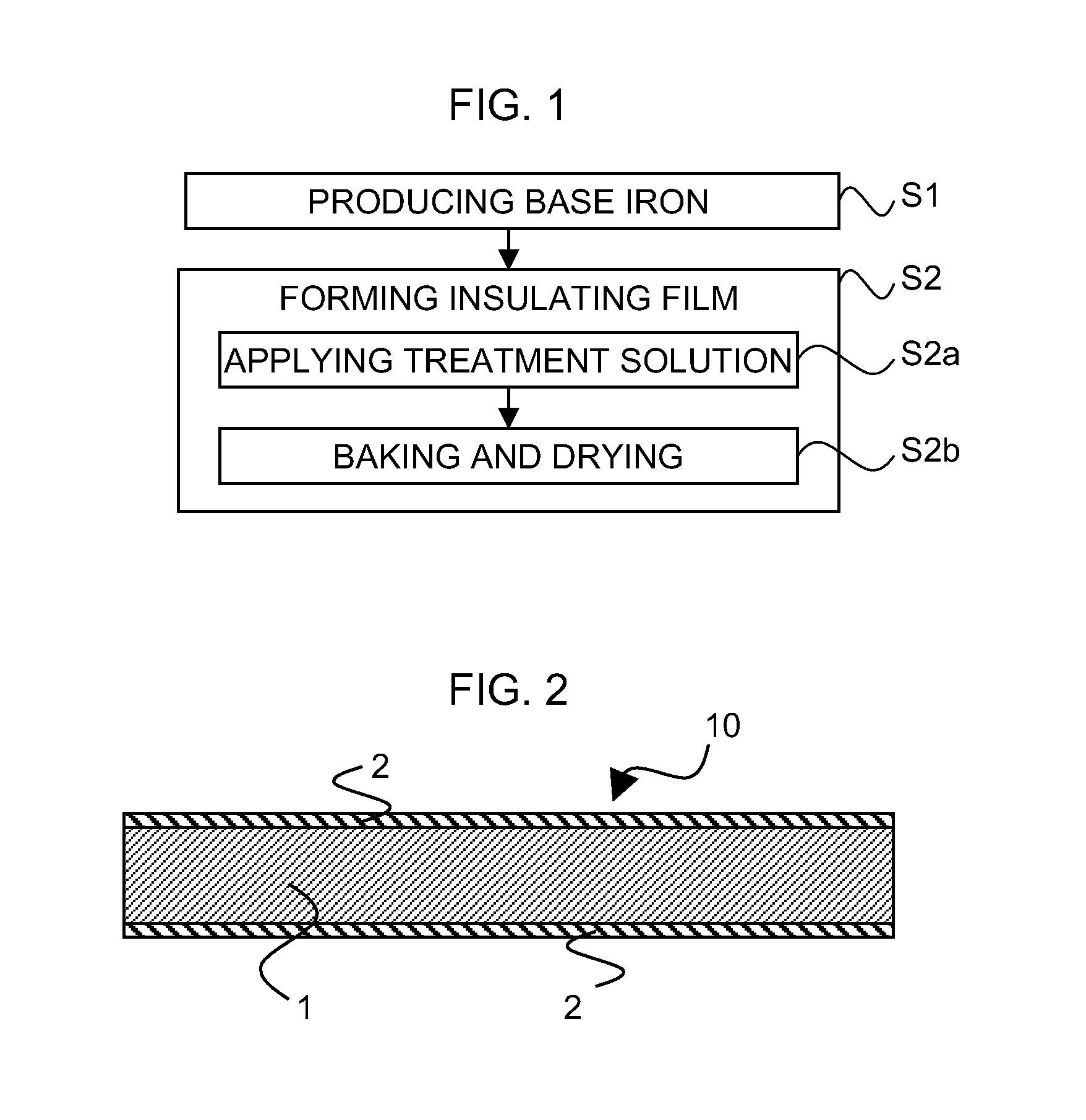
An electrical steel sheet (10) is provided with a base iron (1) and an insulating film (2) formed on a surface of the base iron (1). The insulating film (2) contains: a first component: 100 parts by mass, the first component containing: a metal phosphate: 100 parts by mass; and one kind selected from a group consisting of an acrylic resin, an epoxy resin and a polyester resin which have an average particle size of 0.05 μm to 0.50 μm, or a mixture or copolymer of two or three kinds selected from the group: 1 part by mass to 50 parts by mass; and a second component composed of dispersion or powder of a fluorine resin having an average particle size of 0.05 μm to 0.35 μm: 0.5 parts by mass to 10 parts by mass.

Description

TECHNICAL FIELD[0001]The present invention relates to an electrical steel sheet suitable for a material of an iron core of an electric equipment and so on and a method for manufacturing the same.BACKGROUND ART[0002]When a motor and a transformer are manufactured by using an electrical steel sheet, the electrical steel sheet in a hoop shape is punched into a predetermined shape, and thereafter, electrical steel sheets are laminated and fixed so as to manufacture a laminated iron core. Thereafter, a copper wire is wound around teeth or the like of the laminated iron core. Then, there is a case when a resin molding is performed aiming for improvement of durability, weather resistance, and so on according to usages thereof.[0003]It is important to closely adhere a molding resin to the laminated iron core. This is because objects such as the improvement in durability and weather resistance cannot be attained if the molding resin does not closely adhere to the laminated iron core. Besides...

Claims


Application Information

Patent Timeline
IPC IPC(8): H01B7/02B05D3/02C09D7/61C09D7/65
CPCB05D7/14Y10T428/254C09D7/1216C09D7/125C09D7/1266C09D7/1275C21D8/1283C21D9/46C21D2201/05C21D2211/005C22C38/02C22C38/04C22C38/06H01F1/18C21D8/12B05D3/0254H01B7/02B05D2502/00B05D2504/00B05D2506/10C09D5/084C23C22/74C09D7/61C09D7/65C09D7/67C09D7/68C09D1/00C09D127/18C09D167/00C09D127/12C09D133/00C09D163/00C09D127/04C09D7/40C08K2003/2237C08K2003/2258B05D2508/00C08K2003/026Y10T428/31511Y10T428/3154Y10T428/31529Y10T428/31681Y10T428/31699
Inventor TAKEDA, KAZUTOSHIKOSUGE, KENJITAKASE, TATSUYAMUNEDA, KOHJI
Owner NIPPON STEEL CORP
Learn More