Laser heating system

a technology of laser heating system and laser head, which is applied in the direction of engine starters, electric control, combustion air/fuel air treatment, etc., can solve the problems of unstable combustion events, poor emissions, and reduced fuel economy, and achieve the effect of reducing fuel economy and poor emissions

Inactive Publication Date: 2013-05-16
FORD GLOBAL TECH LLC
View PDF5 Cites 9 Cited by
  • Summary
  • Abstract
  • Description
  • Claims
  • Application Information

AI Technical Summary

Benefits of technology

[0002]Efficient combustion in a cylinder of an engine may depend on a number of factors, including complete vaporization of the fuel and homogenization of the vaporized fuel with the intake air. Incomplete vaporization and / or mixing may lead to reduced fuel economy, poor emissions, and unstable combustion events, such as misfire.

Problems solved by technology

Incomplete vaporization and / or mixing may lead to reduced fuel economy, poor emissions, and unstable combustion events, such as misfire.
Fuel may be heated prior to reaching the cylinder, however, this may actually reduce engine efficiency, as the heat may escape to other components, such as the fuel line.
Further, heating fuel outside of the cylinder may increase the risk of explosion, due to the volatile nature of the fuel.

Method used


Image

  • Laser heating system
  • Laser heating system
  • Laser heating system

Examples


Embodiment Construction

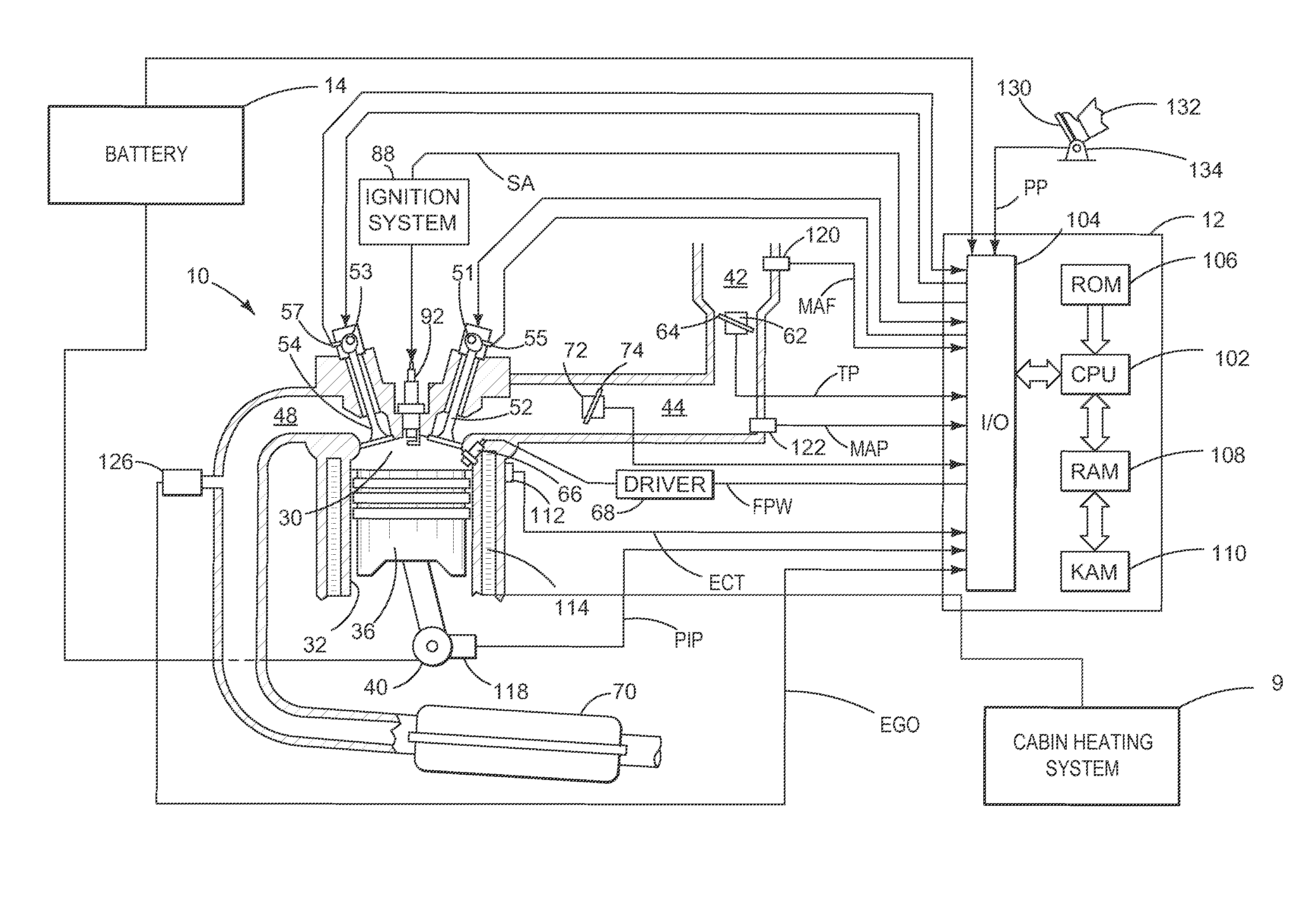
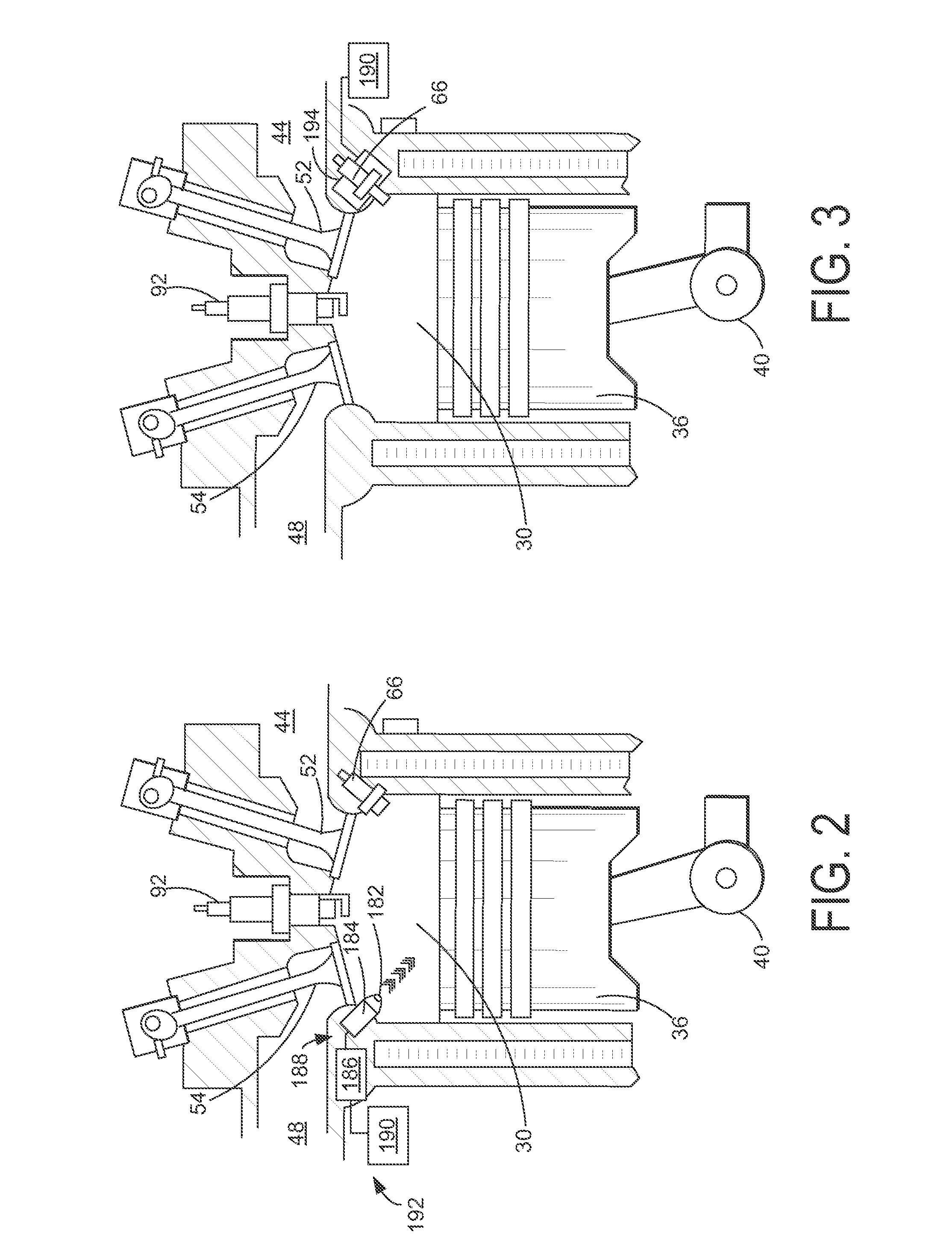
[0017]To improve fuel vaporization, particularly during cold engine conditions, radiation may be used to direct heat to injected fuel, improving fuel vaporization without igniting the fuel. FIG. 1 shows an example engine including a cylinder, spark ignition system, and fuel injector. FIGS. 2-4 show various embodiments of the cylinder of FIG. 1 including a mechanism for heating the fuel in the cylinder via radiation and a mechanism for heating fuel in an injector via a laser heater. FIGS. 5-9 illustrate various control routines that may be carried out by a control system of the engine of FIG. 1.

[0018]Referring specifically to FIG. 1, it includes a schematic diagram showing one cylinder of multi-cylinder internal combustion engine 10. Engine 10 may be controlled at least partially by a control system including controller 12 and by input from a vehicle operator 132 via an input device 130. In this example, input device 130 includes an accelerator pedal and a pedal position sensor 134 f...


PUM


Abstract

A method for vaporizing fuel is provided. The method comprises heating the fuel in a cylinder of an engine via radiation to vaporize the fuel without ignition. In this way, the fuel may be heated to increase vaporization efficiency prior to ignition.

Description

FIELD[0001]The present disclosure relates to a laser for heating fuel in an engine.BACKGROUND AND SUMMARY[0002]Efficient combustion in a cylinder of an engine may depend on a number of factors, including complete vaporization of the fuel and homogenization of the vaporized fuel with the intake air. Incomplete vaporization and / or mixing may lead to reduced fuel economy, poor emissions, and unstable combustion events, such as misfire.[0003]Various approaches have been taken to improve combustion efficiency. Fuel may be heated prior to reaching the cylinder, however, this may actually reduce engine efficiency, as the heat may escape to other components, such as the fuel line. Further, heating fuel outside of the cylinder may increase the risk of explosion, due to the volatile nature of the fuel.[0004]The inventors have recognized the issues with the above approaches and offer a method to at least partly address them. In one embodiment, a method for vaporizing fuel comprises heating the...

Claims


Application Information

Patent Timeline
Patent Type & Authority Applications(United States)
IPC IPC(8): F02M27/06F02M31/02F02M27/00
CPCF02B23/104Y02T10/36F02M31/18F02D13/0207F02D13/0219F02D19/084F02B2075/125F02D41/047F02D41/064F02N19/04F02D2200/0606F02D2250/02Y02T10/125Y02T10/123Y02T10/126F02M27/06F02M31/183Y02T10/12Y02T10/30
Inventor MARTIN, DOUGLAS RAYMONDMILLER, KENNETH JAMES
Owner FORD GLOBAL TECH LLC
Why Eureka
Try Eureka