Biological sample immobilizing apparatus

a technology of immobilizing apparatus and biological sample, which is applied in the direction of diaphragms, electrostatic separation, solid separation, etc., can solve the problem that information about the individuals of a biological sample (for example, individual cells) cannot be obtained from the analysis result obtained by the conventional method, and achieve the effect of analyzing more appropriately and obtaining more biological samples

Inactive Publication Date: 2013-05-16
TOSOH CORP
View PDF5 Cites 52 Cited by
  • Summary
  • Abstract
  • Description
  • Claims
  • Application Information

AI Technical Summary

Benefits of technology

[0077]The apparatus of the present invention provides the following effects.
[0078](1) The apparatus of the present invention makes it possible to quickly immobilize one individual of the biological sample to one holding portion (through-hole) provided in the holding unit. In particular, in the embodiment in which the holding unit is composed of the insulator provided with the plurality of through-holes arranged in the array form as the holding portions, a plurality of individuals of the biological sample can be quickly immobilized one by one to the holding portions (through-holes) arranged in the array form. Also, in the embodiment in which the pair of electrodes is arranged on the common flat surface, it is possible to contemplate the miniaturization of the power source required to apply the AC voltage.
[0079](2) The apparatus of the present invention makes it possible to simultaneously analyze a plurality of individuals of the biological sample one by one while immobilizing the biological sample to the holding portions (through-holes). In particular, in the embodiment in which the pair of electrodes is arranged on the common flat surface, it is also possible to adopt such an embodiment that no structure to serve as the lid is installed to the upper portion of the apparatus, and hence, the biological sample can be analyzed more appropriately.
[0080](3) The apparatus of the present invention makes it possible to collect the gene product derived from the biological sample immobilized to the holding portion (through-hole). In particular, in the embodiment in which the pair of electrodes is arranged on the common flat surface, it is also possible to adopt such an embodiment that no structure to serve as the lid is installed to the upper portion of the apparatus, and hence, the biological sample can be obtained more easily.

Problems solved by technology

Therefore, a problem arises such that any information about the individuals of a biological sample (for example, individual cells) cannot be obtained from the analysis result obtained by the conventional method.

Method used


Image

  • Biological sample immobilizing apparatus
  • Biological sample immobilizing apparatus
  • Biological sample immobilizing apparatus

Examples


example 1

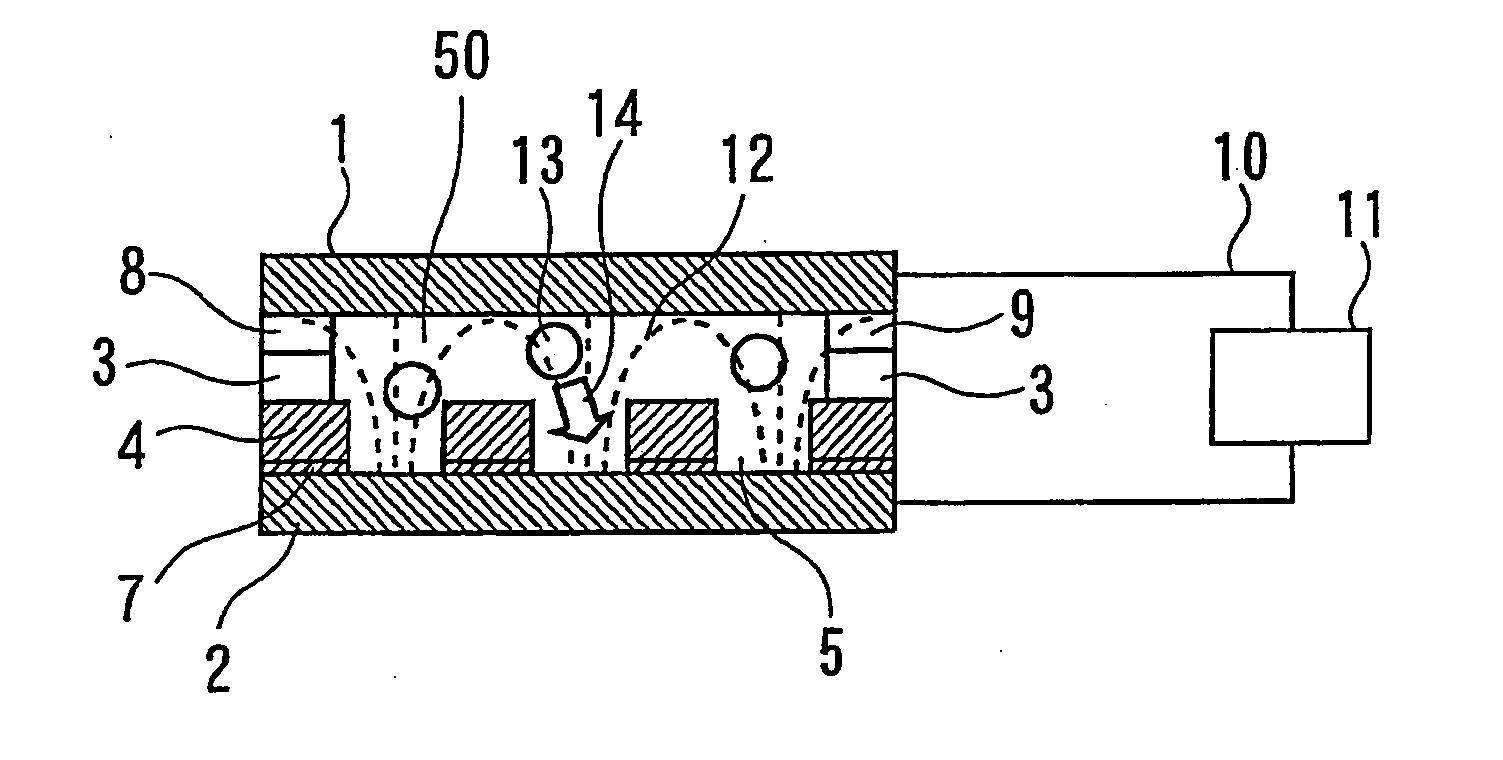
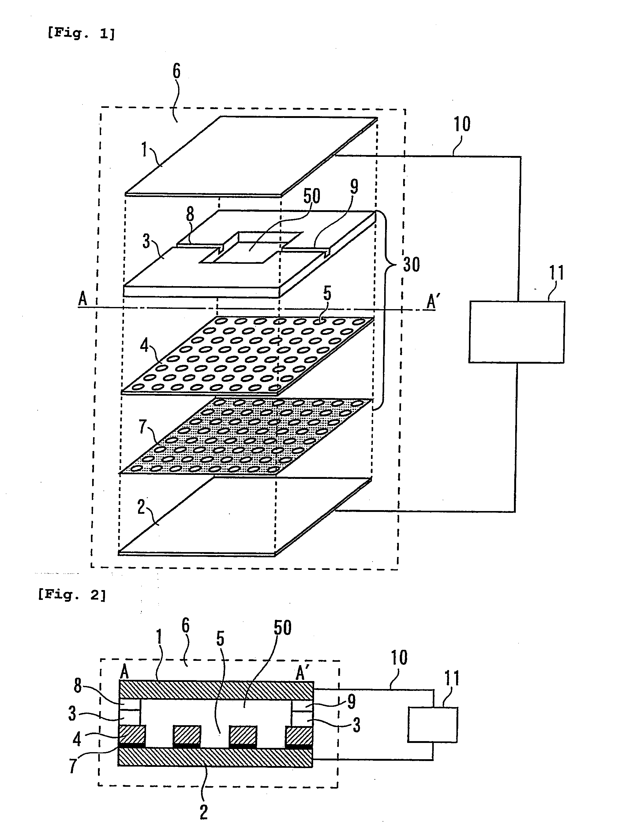
[0104]In Example 1, an apparatus was used, which had such a structure that a spacer 3 was arranged between an upper electrode substrate 1 and a lower electrode substrate 2, and a holding unit composed of a light shielding member 7 and an insulator 4 arranged with a plurality of circular holding portions (through-holes 5) in an array form was interposed by the spacer and the lower electrode as shown in FIG. 11.

[0105]A glass substrate having length 78 mm×breadth 56 mm×thickness 1 mm was used for the electrode substrate. The spacer 3 was prepared with Araldite (registered trademark) resin so that a space of length 20 mm×breadth 20 mm×thickness 1.5 mm was formed on the lower electrode substrate. The spacer was provided with an introducing port 8 and a discharge port 9 for introducing and discharging the suspension containing the biological sample.

[0106]The insulator 4 provided with the plurality of holding portions (through-holes 5) was formed integrally with the lower electrode on the ...

example 2

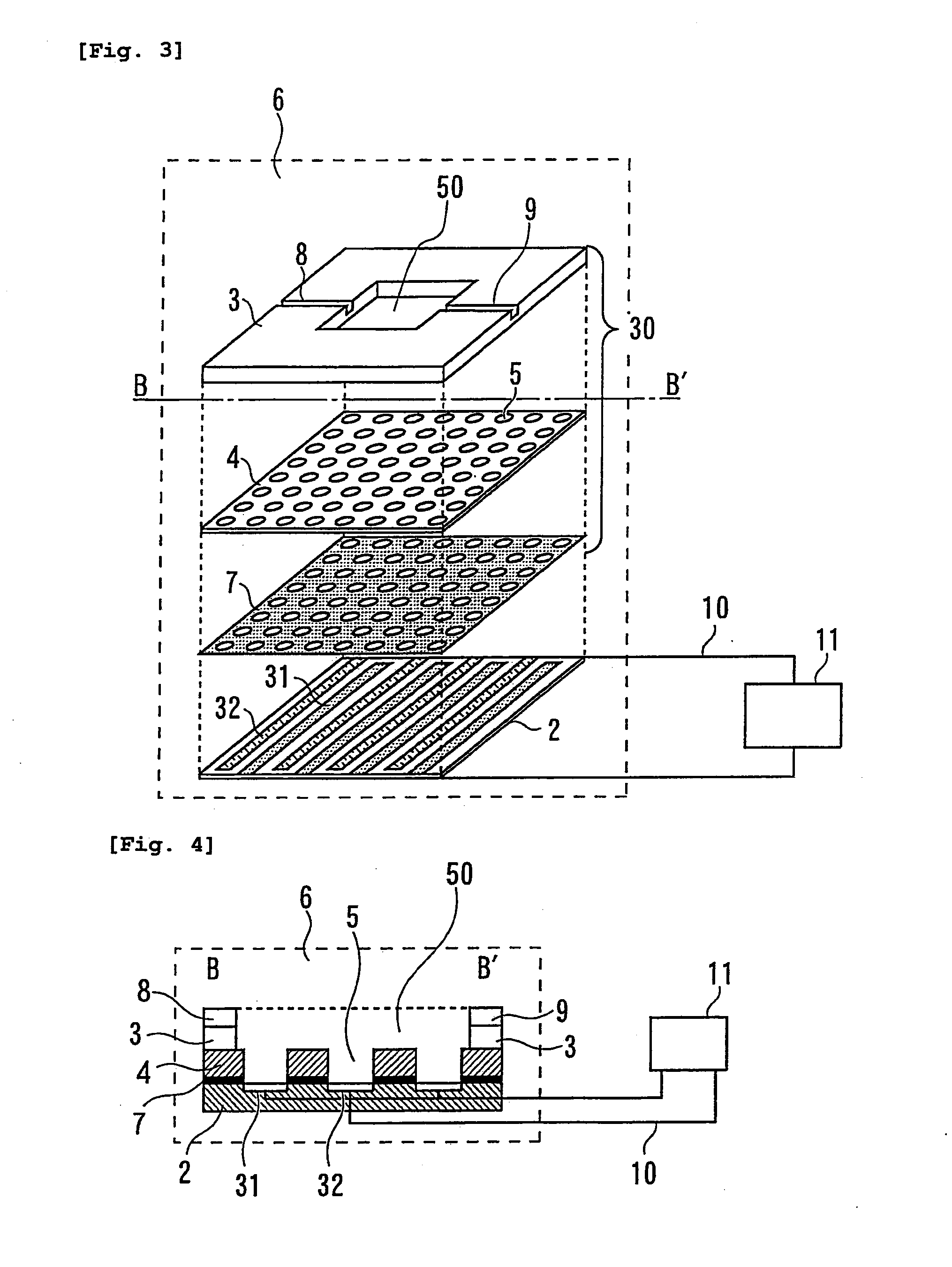
[0118]Next, in Example 2, an apparatus shown in FIGS. 3 and 4 will be referred to, which has such a structure that a pair of electrodes 31 and 32 is provided on one side with respect to the suspension containing the biological sample, i.e., such a structure that a comb-shaped electrode pair is provided. In Example 2, a glass substrate having length 70 mm×breadth 40 mm×thickness 1 mm was used for the substrate on which the pair of electrodes was to be arranged. The spacer 3 was manufactured by cutting out a central portion of length 20 mm×breadth 20 mm from a silicon sheet having length 40 mm×breadth 40 mm×thickness 1.5 mm. An introducing port 8 and a discharge port 9 for introducing and discharging the suspension containing the biological sample were provided for the spacer 3. A holding unit having a plurality of holding portions (through-holes) 5 and the pair of electrodes 31 and 32 were formed integrally on the glass substrate in accordance with a method based on the photolithogra...

example 3

[0127]Next, in Example 3, an apparatus shown in FIG. 4B will be referred to, which has such a structure that a pair of electrodes 31 and 32 is provided on one side with respect to the suspension containing the biological sample, i.e., such a structure that a comb-shaped electrode pair is provided, wherein the electrodes are arranged in a stepped form on the substrate. In Example 3, in the same manner as in Example 2, a glass substrate 60 having length 70 mm×breadth 40 mm×thickness 1 mm was used for the substrate on which the pair of electrodes was to be arranged. However, the surface of the glass substrate 60 is processed in accordance with a technique or the like in which the etching rate is changed, and thereby stepped portions (or grooves) are formed on the surface. The stepped portions provide the stepped form in which the electrodes are to be arranged. The spacer 3 and the introducing port 8 and the discharge port 9 provided for the spacer 3 are similar to those of Example 2. I...


PUM

PropertyMeasurementUnit
distanceaaaaaaaaaa
distanceaaaaaaaaaa
frequencyaaaaaaaaaa

Abstract

A biological sample immobilizing apparatus is provided, comprising a holding unit which holds a biological sample, a pair of electrodes which allows a dielectrophoretic force to act on the biological sample to move the biological sample to the holding unit, and a power source which applies an AC voltage to the pair of electrodes. Accordingly, a plurality of components contained in the biological sample can be conveniently separated into individuals one by one and respective genes thereof can be analyzed one by one quickly and simultaneously, while providing a high density and being miniaturized.

Description

TECHNICAL FIELD[0001]The present invention relates to a biological sample immobilizing apparatus (an apparatus for immobilizing a biological sample).BACKGROUND ART[0002]Genetic factors and environmental factors are involved in various diseases. Regarding certain diseases such as congenital metabolic disorder, cancer, diabetes, hypertonia, Alzheimer's disease, autoimmune disease, obesity, and alcoholism, the involvement of a genetic factor, i.e. the involvement of a gene, is responsible for the disease at a large proportion. In recent years, due to the rapid progress in the molecular biology, the involvement of a genetic factor is concretely elucidated in relation to various diseases. Also, attention is focused on the early detection and the medical treatment of a disease on the basis of the analysis that targets genes.[0003]Further, for example, it is known that in the case of a certain type of disease, cells having a property specific to the disease exist, such as the following: ca...

Claims


Application Information

Patent Timeline
Patent Type & Authority Applications(United States)
IPC IPC(8): G01N27/447
CPCB01L3/502761B01L2200/0668B01L2300/0816B01L2400/0424B03C5/005B03C5/026B01J2219/00653B01L2300/0819G01N27/44756C12M33/00B01J2219/00317B01J2219/00648B03C2201/26
Inventor MORIMOTO, ATSUSHIFUTAMI, TORUMOGAMI, TOSHIFUMI
Owner TOSOH CORP
Why Eureka
Try Eureka