
Short arc welding system

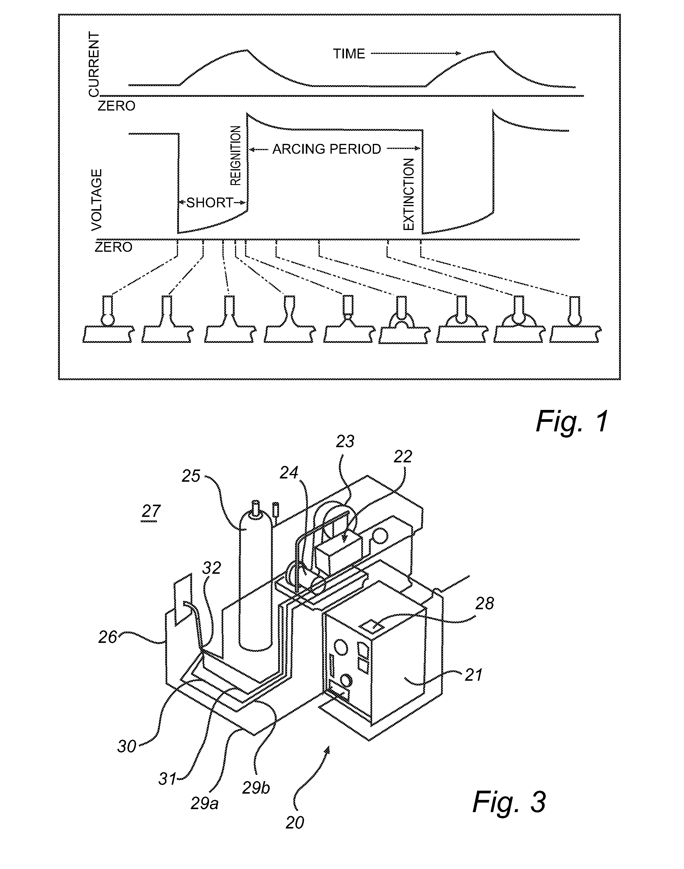
Active Publication Date: 2013-05-16
ESAB AB
View PDF94 Cites 5 Cited by
  • Summary
  • Abstract
  • Description
  • Claims
  • Application Information

AI Technical Summary

Benefits of technology

The invention provides a system for controlling a weld-current in a direct current apparatus for short arc welding. The system allows for accurate control at both the arc phase and the short circuit phase of short arc welding. By separating the ramp generator and current regulator in the voltage feedback loop and arranging them in parallel, the precise control of the reference current is facilitated without influence from a randomly appearing open circuit state. The method also enables good control of the shape of the current ramp during short circuit phase, while enabling a straight forward control of voltage during the arc phase. The invention prevents drift of the reference current due to the high voltage between the electrode and the work piece at open circuit state.

Problems solved by technology

“Straight” polarity, is less frequently used because of poor transfer of molten metal from the wire electrode to the work piece.
This mode of metal transfer can be erratic, with spatter and fumes being common.
Pulsed arc welding requires complex and expensive welding apparatuses.
The control of the welding process in short circuit phase and arc phase is challenging, and the occurrence of open circuit state adds to the complexity of controlling the short arc welding process.
Open circuit state is normally undesired and has a random appearance.
This leads to difficulty of control of the arc and short circuit state since the voltage regulator will have an influence on the current raise limiter and vice versa.

Method used


Image

  • Short arc welding system
  • Short arc welding system
  • Short arc welding system

Examples


Embodiment Construction

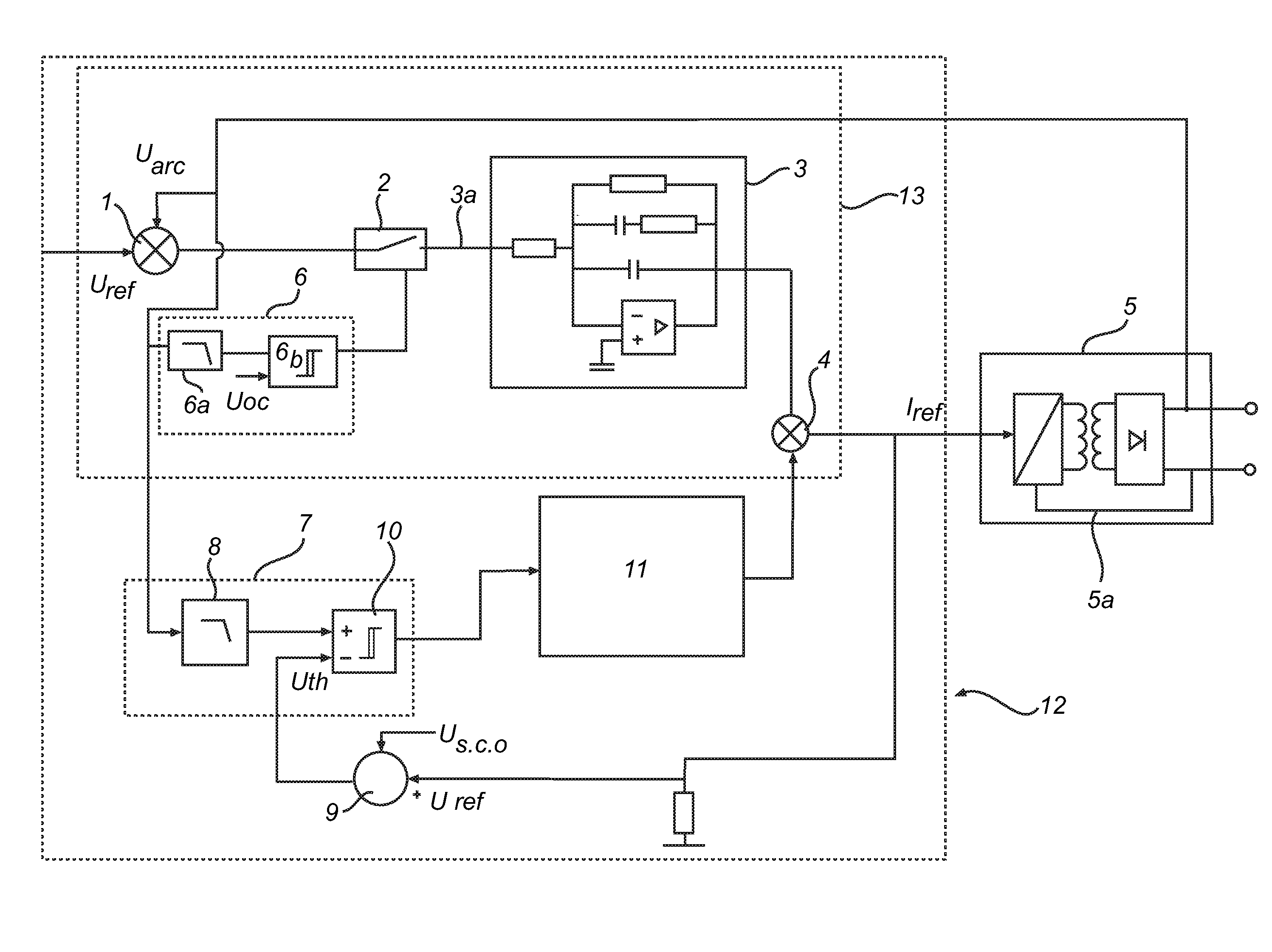
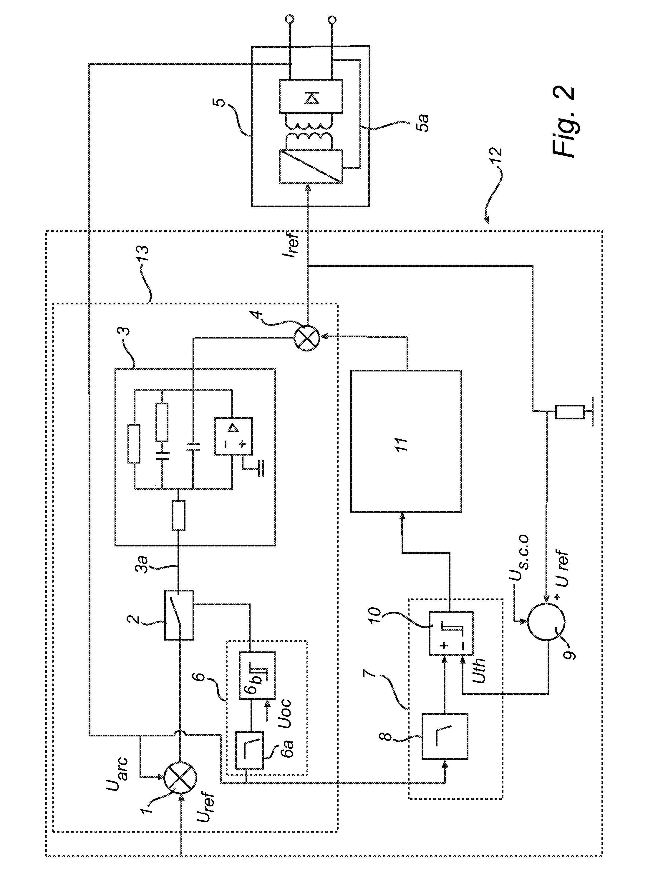
[0047]FIG. 2 shows a system 12 for controlling a weld-current in an arc welding apparatus 20 (FIG. 3) for short arc welding.

[0048]A voltage feedback loop 13 controls the voltage at a welding electrode connected to a constant current power source.

[0049]The constant current power source includes a current feedback loop 5a which compares an output current with a reference current provided from a system 12 for controlling a weld-current in the arc welding apparatus 20 (FIG. 3). A current regulator included in the constant current power supply 5 controls the output current of the power supply in dependence of a regulation error between the reference current and the output current.

[0050]The voltage feedback loop 13 includes a subtraction node 1 where the output voltage Uarc is subtracted from the reference voltage Uref in the node 1. The difference between the output voltage Uarc and the reference voltage Uref constitutes a regulation error E, which is delivered to the PI regulator 3 as a...


PUM

PropertyMeasurementUnit
Currentaaaaaaaaaa
Electric potential / voltageaaaaaaaaaa

Abstract

A system for controlling a weld-current in an arc welding apparatus for short arc welding comprising a current regulator included in a voltage feedback loop from a power supply to a welding electrode and a ramp generator arranged to provide current ramps during a short circuit phase at said welding electrode.

Description

FIELD OF INVENTION[0001]The present invention relates to a system for controlling a weld-current in a direct current arc welding apparatus for short arc welding. The present invention in particular relates to a system for controlling a weld-current in an direct current arc welding apparatus for short arc welding comprising a current regulator included in a voltage feedback loop, and a ramp generator arranged to provide current ramps during a short circuit. The invention furthermore relates to a method for controlling a power source.BACKGROUND OF INVENTION[0002]The present invention relates to a system for controlling a weld-current in a direct current arc welding apparatus for short arc welding. Short arc welding is a metal transfer mode in gas metal arc welding where a drop of molten metal will dip into a weld pool before detachment from a consumable electrode in a process of metal transfer.[0003]In gas metal arc welding a consumable electrode is continuously fed towards a welding ...

Claims


Application Information

Patent Timeline
IPC IPC(8): B23K9/095
CPCB23K9/073B23K9/1006B23K9/095B23K9/091B23K9/09B23K9/10
Inventor MNICH, ANDRZEJ
Owner ESAB AB
Learn More