Load-bearing structures for aircraft engines and processes therefor

a technology for aircraft engines and load bearings, applied in the direction of machines/engines, applications, machine supports, etc., can solve the problems of complicated cost-effectiveness of producing brackets from these materials, limited production range of pmcs formed with thermoplastic matrix materials, and cost prohibitive use of traditional thermoset resins to produce pmc brackets. , to achieve the effect of constant cross-sectional thickness, constant cross-sectional thickness, and constant cross-sectional thickness

Inactive Publication Date: 2013-05-16
GENERAL ELECTRIC CO
View PDF10 Cites 23 Cited by
  • Summary
  • Abstract
  • Description
  • Claims
  • Application Information

AI Technical Summary

Benefits of technology

[0007]According to a first aspect of the invention, a process of fabricating a load-bearing structure includes producing at least a first shaped panel that has a substantially constant cross-sectional thickness and has at least first and second portions that lie in different planes and are interconnected by at least a first bend therebetween. The first shaped panel is formed by thermoforming a polymer matrix composite material comprising a thermoplastic resin reinforced with a continuous fiber reinforcement material. The first shaped panel is then machined to alter its shape. The machining step may directly produce the load-bearing bracket from the first shaped panel. Alternatively, the machining step may produce at least a first subcomponent from the first shaped panel, and the process further entails a joining operation with the result that the first subcomponent forms part of the load-bearing bracket. Yet another alternative is for the machining step to produce multiple separate subcomponents from the first shaped panel, at least some of which then undergo a joining operation to form the load-bearing bracket. The resulting bracket can then be installed on an aircraft engine to secure a component to the aircraft engine.
[0008]A second aspect of the invention is a process that includes producing at least first and second flat panels of a polymer matrix composite material comprising a thermoplastic resin reinforced with a continuous fiber reinforcement material, in which each of the flat panels has a substantially constant cross-sectional thickness and is flat so as to lie in a single plane. At least one of the flat panels is then thermoformed to form at least a first shaped panel having a substantially constant cross-sectional thickness and having at least first and second portions that lie in different planes and are interconnected by at least a first bend therebetween. The first shaped panel is then machined to alter its shape and produce at least a first subcomponent therefrom. A load-bearing bracket is then produced by joining the first subcomponent to a second subcomponent defined by the second flat panel or a second shaped panel produced by thermoforming the second flat panel, after which the load-bearing bracket can be installed on an aircraft engine to secure a component to the aircraft engine.
[0009]Additional aspects of the invention include load-bearing brackets that are produced by the steps of one of the processes described above. However, more generally, the invention broadly encompasses aircraft engine brackets that are formed of a polymer matrix composite material that comprises a continuous fiber reinforcement material in a thermoplastic resin matrix material. As a more particular example, such an aircraft engine bracket includes at least first and second subcomponents that are joined together to form the bracket. Each subcomponent is formed of a polymer matrix material comprising a continuous fiber reinforcement material in a thermoplastic resin matrix material, and each subcomponent has a substantially constant cross-sectional thickness. At least one of the subcomponents is machined from at least one shaped panel that was thermoformed to have at least first and second portions that lie in different planes and are interconnected by at least a first bend therebetween.

Problems solved by technology

However, a challenge has been the identification of material systems that have acceptable properties yet can be produced by manufacturing methods to yield a cost-effective PMC component.
Though considerable weight savings could be realized by fabricating aircraft engine brackets from PMC materials, performance requirements as well as the size, variability and complexity of such brackets have complicated the ability to cost-effectively produce brackets from these materials.
For example, the use of traditional thermoset resins to produce PMC brackets has been generally viewed as cost prohibitive due to the labor-intensive process and long manufacturing cycle times involved with thermosets, as well as the large number of relatively small brackets having many different part configurations.
On the other hand, PMCs formed with thermoplastic matrix materials are limited by their tendency to soften and lose strength at elevated temperatures.
Another complication is the type of reinforcement system required by PMC materials in aircraft engine applications.
However, hand lay-up processes involved in the use of continuous fiber reinforcement materials further complicate the ability to produce a wide variety of relatively small brackets having complex shapes.
On the other hand, chopped fiber reinforcement systems, whether in a thermoplastic or thermoset resin matrix, are not an ideal solution due to their lower mechanical performance.
In particular, the lower strength of PMC components reinforced with chopped fibers necessitates the fabrication of a relatively thick and heavy bracket.
However, because there is a large number of brackets that have different shapes on aircraft engines, the tooling cost associated with an individual mold being required for each unique bracket generally prohibits this manufacturing approach.

Method used


Image

  • Load-bearing structures for aircraft engines and processes therefor
  • Load-bearing structures for aircraft engines and processes therefor
  • Load-bearing structures for aircraft engines and processes therefor

Examples


Embodiment Construction

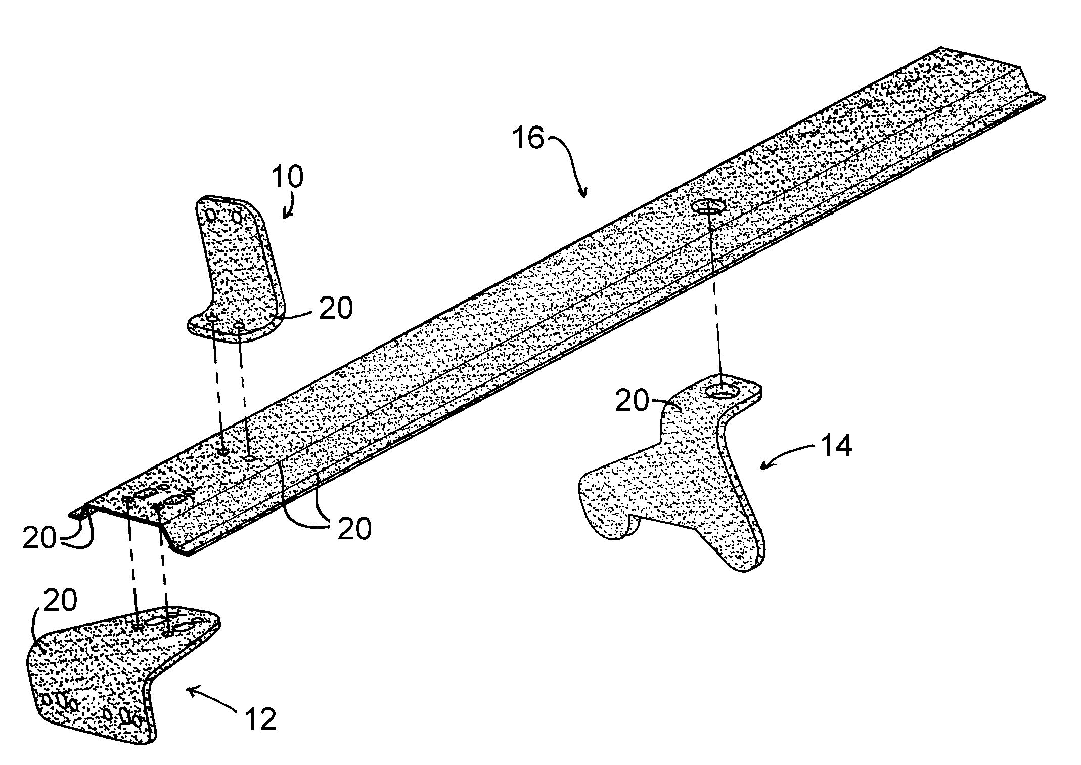
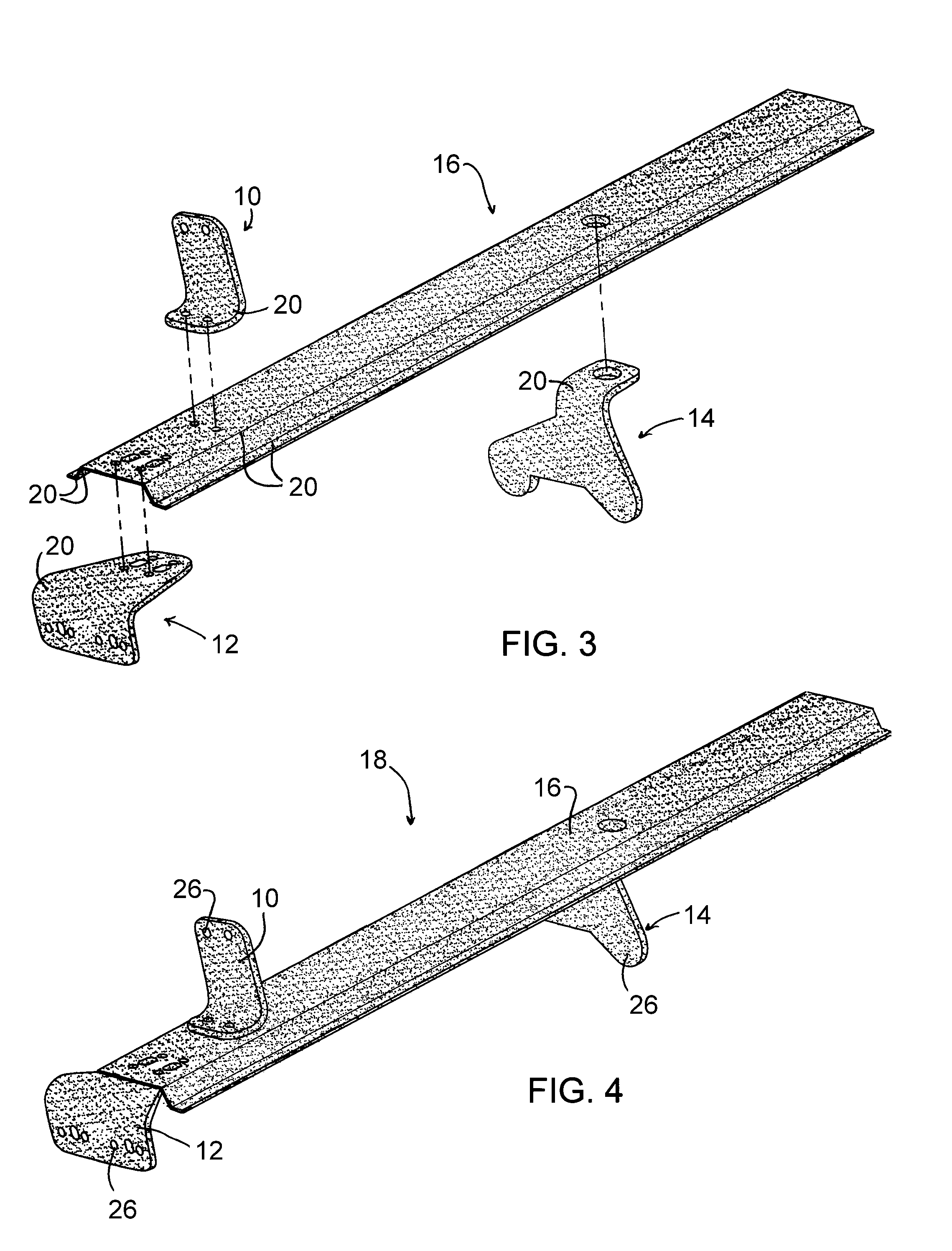
[0018]The present invention will be described in terms of composite load-bearing structures that, though capable of being adapted for use in a wide range of applications, are particularly well suited as brackets whose primary purpose is to support or secure various components of aircraft engines, for example, components within the fan sections of high-bypass gas turbine engines. Particularly notable examples are brackets that are mounted on the exterior of the fan case and support components such as tubes, wiring harnesses, oil tanks, etc. However, various other load-bearing structures and various other applications to which the present invention could be applied are also within the scope of the invention.

[0019]The present invention provides a process by which brackets that exhibit mechanical, chemical and thermal properties (including strength, fatigue resistance, maximum temperature capability, chemical / fluid resistance, etc.) that are suitable for aircraft engine applications and...


PUM

PropertyMeasurementUnit
thicknessaaaaaaaaaa
temperatureaaaaaaaaaa
thicknessaaaaaaaaaa

Abstract

Load-bearing structures constructed from polymer matrix composite (PMC) materials, and processes for their production. The structures are produced from at least one shaped panel formed of a continuous fiber reinforcement in a thermoplastic resin matrix. The shaped panel has been thermoformed to have a substantially constant cross-sectional thickness and portions that lie in different planes and are interconnected by one or more bends. The shaped panel is machined to alter its shape, and optionally to produce multiple separate subcomponents therefrom. The machined shaped panel can constitute the entire structure, or the structure can be formed by joining the machined shaped panel with other shaped panels or by joining two or more of the subcomponents. The structure can be installed on an aircraft engine to secure components to the engine.

Description

BACKGROUND OF THE INVENTION[0001]The present invention generally relates to load-bearing structures and to processes for their production. More particularly, this invention is directed to the use of composite materials in the fabrication of load-bearing structures, as an example, brackets used in aircraft engines.[0002]The maturation of composite technologies has increased the opportunities for the use of composite materials in a wide variety of applications, including but not limited to aircraft engines such as the GE90® and GEnx® commercial engines manufactured by the General Electric Company. Historically, the fabrication of components from composite materials has been driven by the desire to reduce weight, though increases in metal costs have also become a driving factor for some applications.[0003]Composite materials generally comprise a fibrous reinforcement material embedded in a matrix material, such as a polymer or ceramic material. The reinforcement material serves as the ...

Claims


Application Information

Patent Timeline
Patent Type & Authority Applications(United States)
IPC IPC(8): B64D27/26B64D27/00F16M13/00
CPCB29C70/42F05D2300/603B29C69/001B29C51/002B29L2031/737B29C65/34B29C66/112B29C66/524B29C66/532B29L2031/3076B29C65/08B29C65/1412B29C65/48B29C65/562B29C65/60B29C66/131B29C66/71B29C66/7212B29C66/73921B29C65/02B29C65/06B29C66/72141B29C70/545F01D25/00F05D2300/43Y02T50/433Y02T50/672B29C51/12B29K2071/00B29K2079/085B29K2081/04B29K2307/04B29K2309/08B29K2305/00B29K2309/02B29K2277/00B29C66/61B29L2031/7172Y10T29/49789Y10T29/49826Y10T29/49947B29C51/268B29K2101/12B29K2105/0809B29L2009/00B29L2031/003Y02T50/40Y02T50/60B29K2277/10B29K2301/00F16B5/02F16B5/04
Inventor WOLFE, JARED MATTHEWKOSTKA, JAMES MICHAEL
Owner GENERAL ELECTRIC CO
Why Eureka
Try Eureka