Refuel control system and method of refuelling

Inactive Publication Date: 2013-05-16
AIRBUS OPERATIONS LTD
View PDF13 Cites 20 Cited by
  • Summary
  • Abstract
  • Description
  • Claims
  • Application Information

AI Technical Summary

Benefits of technology

[0033]Preferably, the method comprises a step of controlling the refuel valve(s) to gradually close as the indicated amount of fuel in the tank(s) reaches the desired amount of fuel. This minimizes surge pressures within the refuel pipelines and at the refuel valves.
[0034]Preferably, the method comprises th

Problems solved by technology

However, if, at the point when the refuel process should be terminated, there was a failure, refuel may continue, resulting in an overspill of fuel via the tank venting system.
The failure could either be a failure in the fuel level indicator equipment or in the human operative's interpretation

Method used


Image

  • Refuel control system and method of refuelling
  • Refuel control system and method of refuelling
  • Refuel control system and method of refuelling

Examples


Embodiment Construction

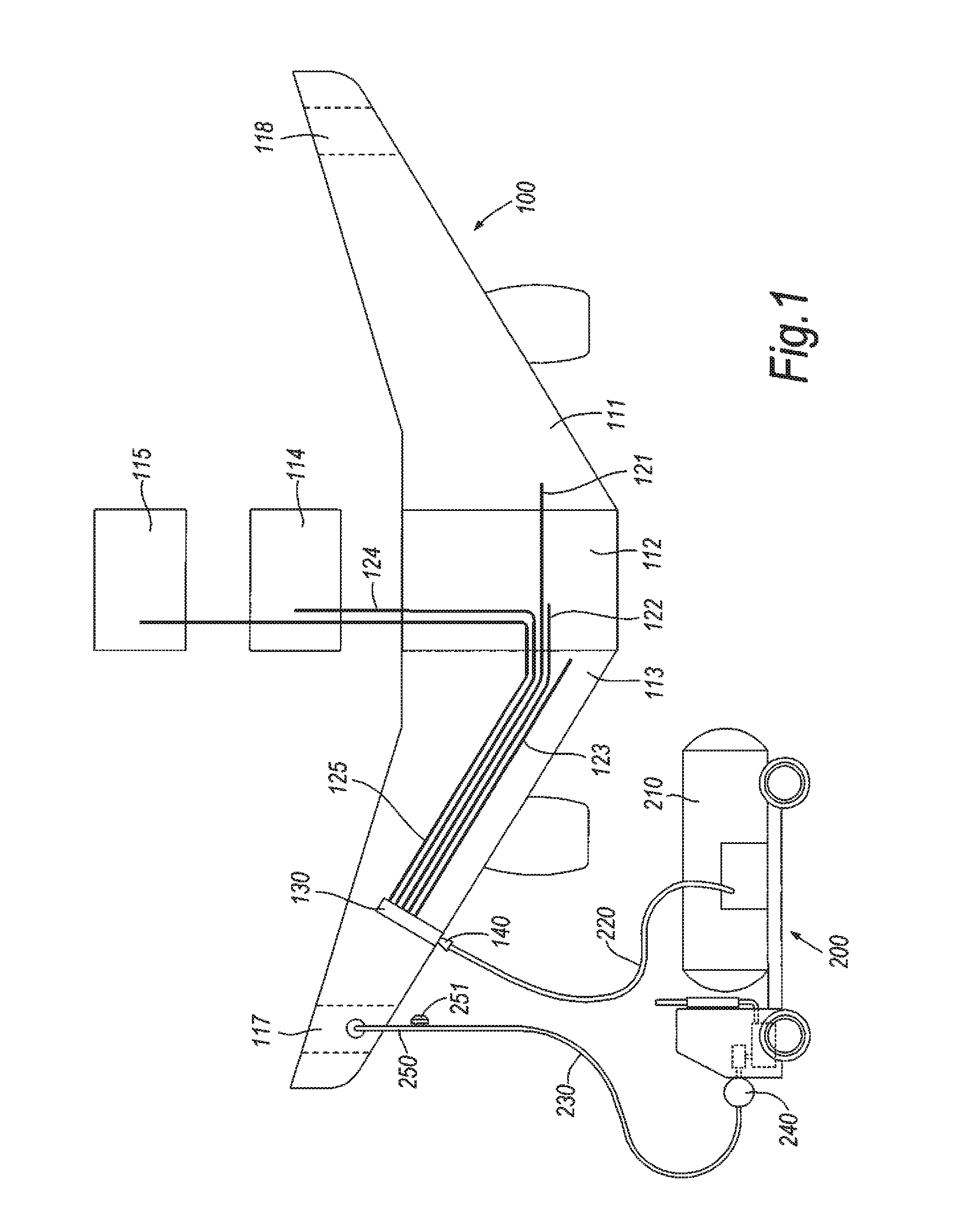
[0041]FIG. 1 shows, schematically, an aircraft 100 with a left tank 111 in the left wing (the wing on the left when viewed looking forward in the aircraft), a centre tank 112 and a right tank 113. It also has a first auxiliary tank 114 and a second auxiliary tank 115 located in the body of the aircraft. In addition, the aircraft 100 has a surge / vent tank in the outboard region of each wing. The surge tank in the left wing is labelled 118 and the surge tank in the right wing is labelled 117. The tanks, collectively, are labelled 110.

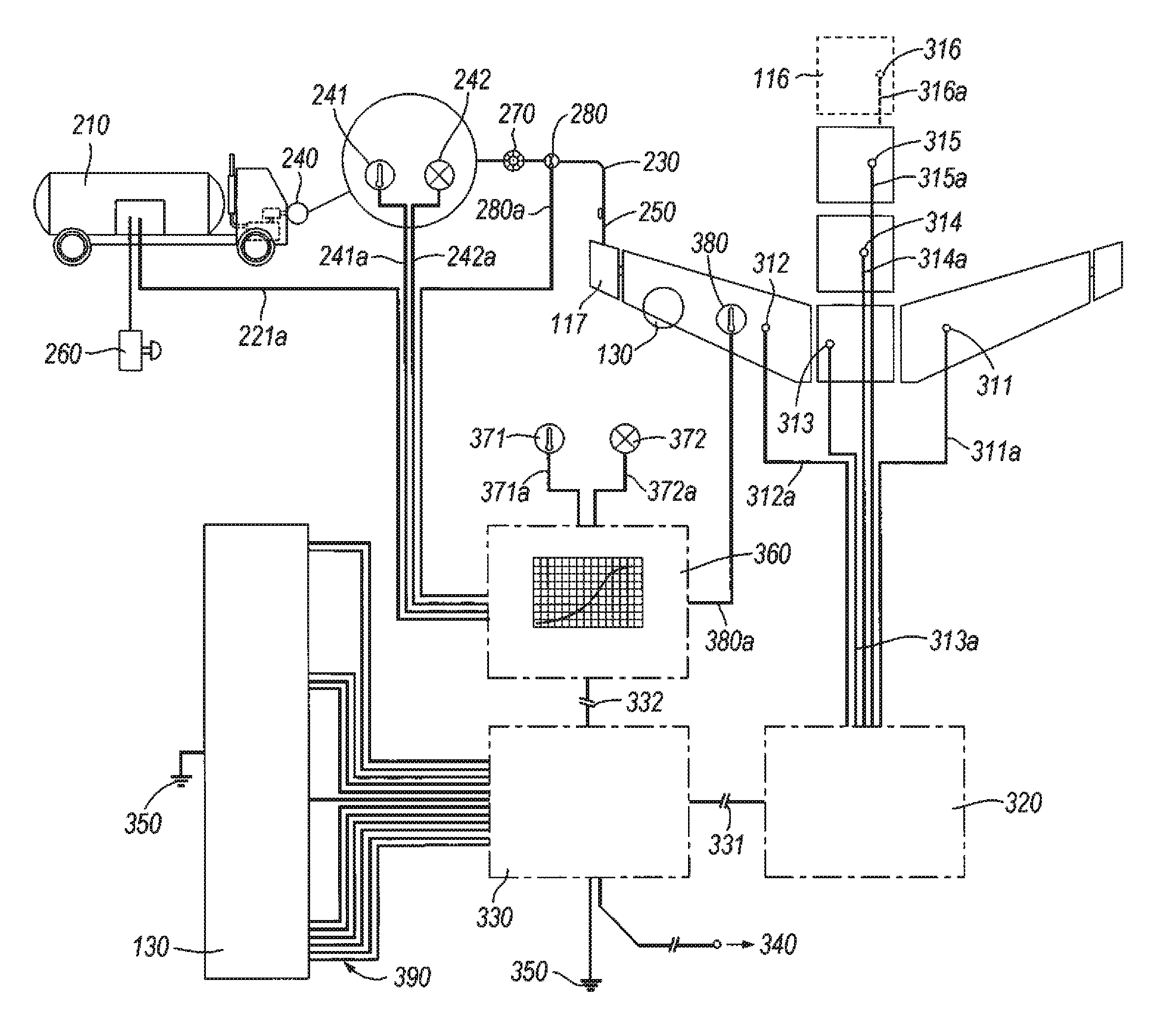
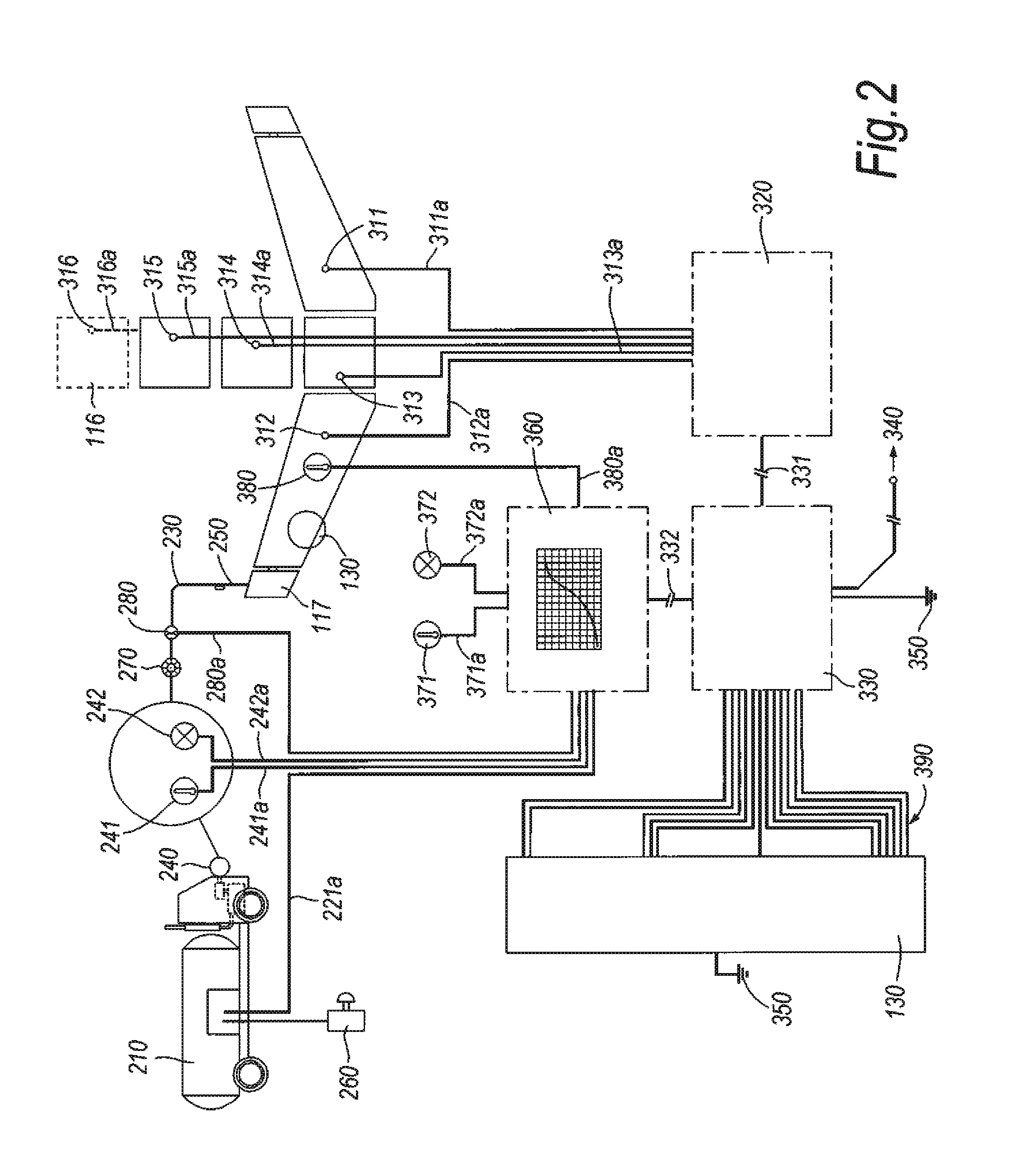
[0042]Each tank 110 has a separate refuel line 120 leading to it from a refuel coupling 140 and valve assembly 130. The refuel line to the left tank is labelled 121, the refuel line to the centre tank 122, to the right tank 123, to the first auxiliary tank 124 and to the second auxiliary tank 125.

[0043]Each refuel line 120 associated with the different tanks 110, has a valve (not shown) associated with it within the valve assembly 130. These valves contro...


PUM


Abstract

The invention provides a refuel control system for controlling refuel of at least one tank (111,112,113, 14,115,116) onanaircraft 100,the refuel control system comprising monitoring apparatus (241, 242, 280, 371, 372, 380, 311, 312, 313, 314, 315, 316, 221) for monitoring data relevant to the refuel process, a control device (330) for receiving said data from the monitoring apparatus, and a refuel valve (130) for controlling flow of fuel to the tank wherein said refuel valve is controllable by the control device such that refuel of the tank can be controlled based on the monitored data. The invention also provides a method of refuelling at least one fuel tank on an aircraft.

Description

BACKGROUND OF THE INVENTION[0001]The present invention concerns a refuel control system. More particularly, but not exclusively, this invention concerns a refuel control system for controlling refuel of at least one tank on an aircraft. The invention also concerns a method of refuelling at least one tank on an aircraft.[0002]Historically, refuel control systems were based predominantly on an interaction between a human operative and a “deadman's” switch. Whilst the human operative held down the “deadman's” switch, fuel was pumped from ground equipment into the tanks of the aircraft through a refuel coupling. Fuel level indicators in the tanks measured the level of fuel in the tanks and this information was fed to the human operative. The human operative could then release the “deadman's” switch when the tanks were full (or approaching being full) and therefore terminate the refuel process.[0003]However, if, at the point when the refuel process should be terminated, there was a failu...

Claims


Application Information

Patent Timeline
IPC IPC(8): B64F1/28
CPCB64F1/28B64D37/16
Inventor FRENCH, CLIVE ROBERT
Owner AIRBUS OPERATIONS LTD
Why Eureka
Try Eureka