
Agile Clocking with Receiver PLL Management

Active Publication Date: 2013-05-16
APPLE INC
View PDF0 Cites 19 Cited by
  • Summary
  • Abstract
  • Description
  • Claims
  • Application Information

AI Technical Summary

Benefits of technology

This patent describes a way to change the frequency of a clock signal in order to reduce interference with other signals in an electronic system. By changing the frequency of the clock signal so that it doesn't match the frequencies of other signals, interference can be minimized. This technology can improve the performance and reliability of electronic systems.

Problems solved by technology

Often times during the operation of such a device, the frequencies of various signals may be deliberately changed during operation.

Method used


Image

  • Agile Clocking with Receiver PLL Management
  • Agile Clocking with Receiver PLL Management
  • Agile Clocking with Receiver PLL Management

Examples


Embodiment Construction

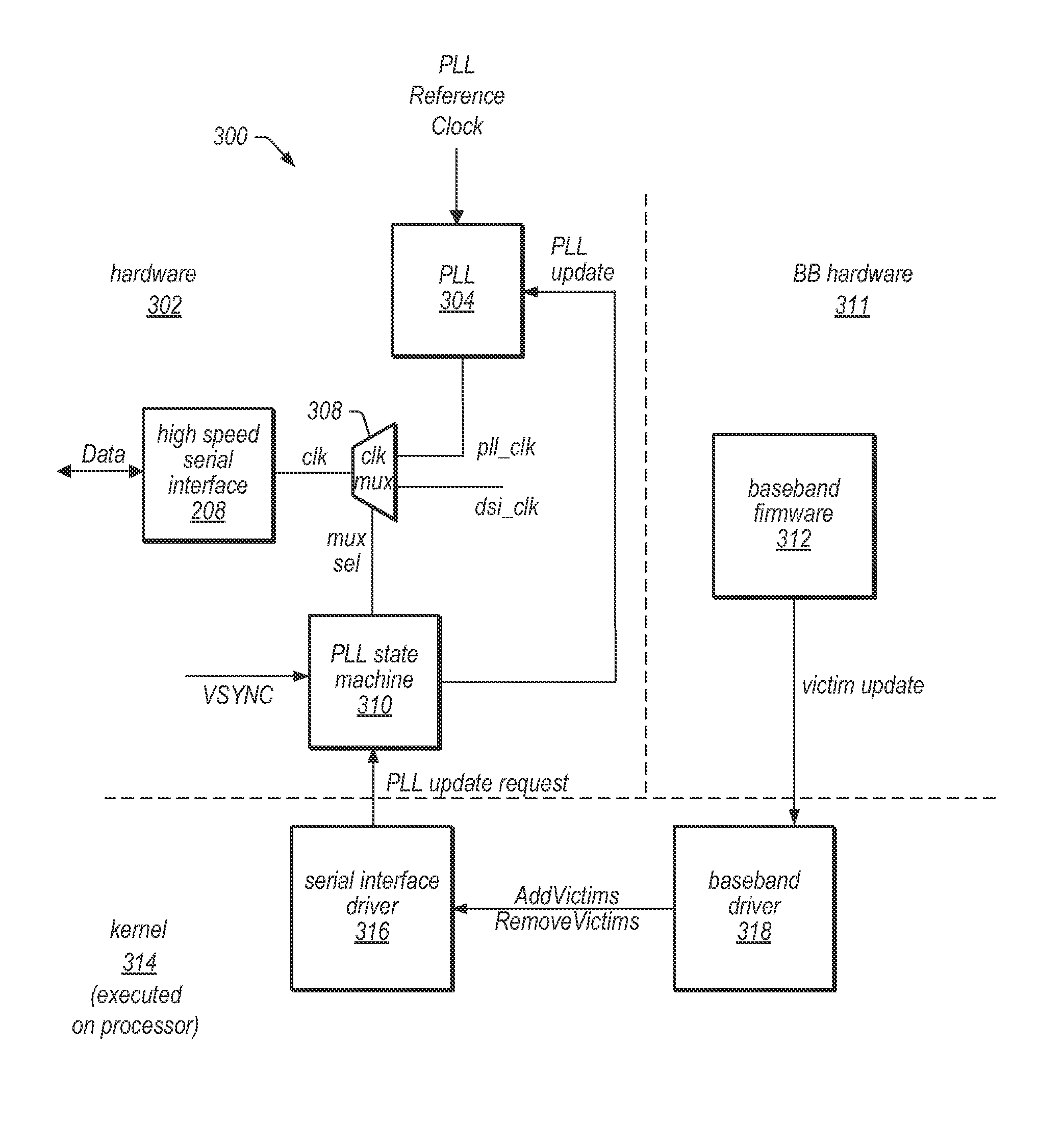
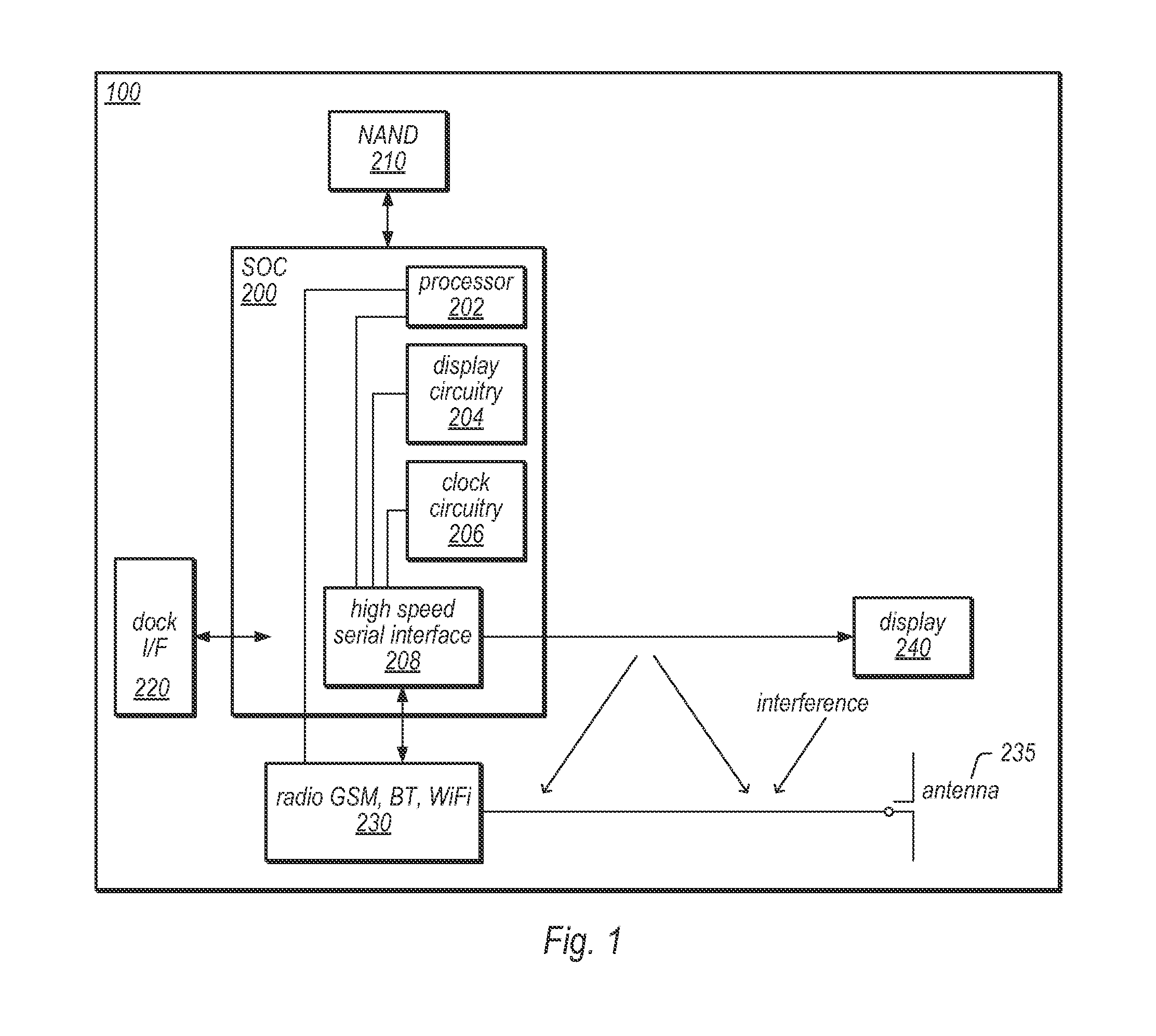
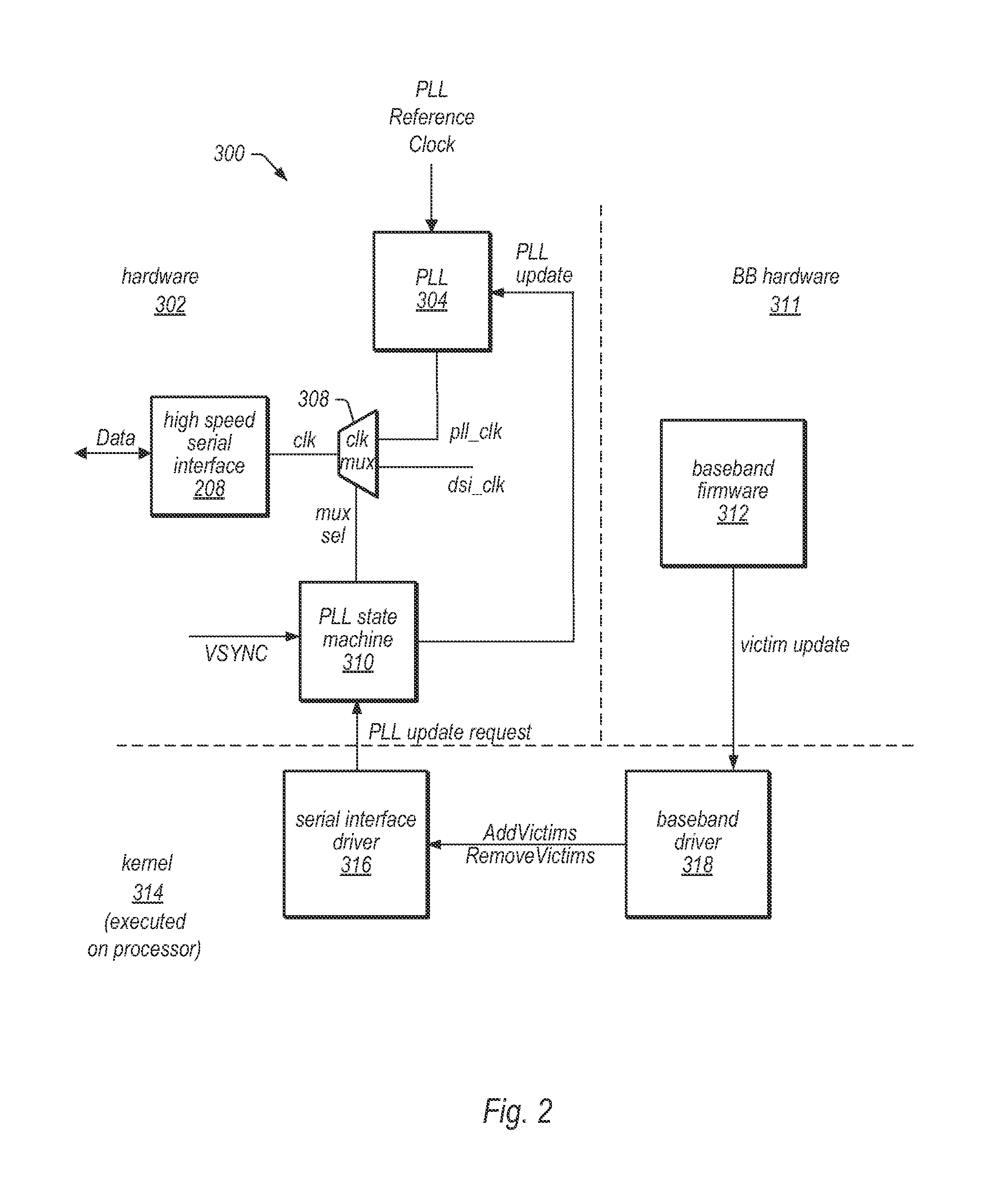
[0018]FIG. 1 illustrates an exemplary device 100, which may implement embodiments described herein. The device 100 may be any of various devices. For example, the device 100 may be a portable or mobile device, such as a mobile phone, PDA, audio / video player, etc. In embodiments described herein, the device 100 may be configured to communicate with other devices (e.g., other wireless devices, wireless peripherals, cell towers, access points, etc.) using one or more wireless channels. As used herein, a “wireless device” refers to a device that is able to communicate with other devices or systems using wireless communication. For example, the device 100 may be configured to utilize one or more wireless protocols, e.g., 802.11x, Bluetooth, WiMax, CDMA, GSM, etc., in order to communicate with the other devices wirelessly. The device 100 may also be configured to adjust and / or change input clocking signals within the device 100 in order to reduce (or eliminate) interference with communica...


PUM


Abstract

A method and apparatus for changing a frequency of a clock signal to avoid interference is disclosed. In one embodiment, data conveyed on a first interface is synchronized to a clock signal at a first frequency. Signals are conveyed on a second interface at another frequency. Responsive to a change of the frequency at which signals are conveyed on a second interface, a clock control unit associated with the first interface initiates a change of the clock signal to a second frequency. The second frequency may be chosen as to not cause interference with the frequency at which signals are conveyed on the second interface. The change of the clock frequency may be performed in such a manner as to prevent spurious activity on the clock line of the interface.

Description

[0001]This application claims priority to U.S. Provisional Application 61 / 559,339, filed on Nov. 14, 2011.TECHNICAL FIELD[0002]The present disclosure relates to the field of electronic devices, and more particularly to the dynamic changing of clock signal frequencies.BACKGROUND DESCRIPTION[0003]In modern electronic devices and systems, many signals are conveyed between various functional units, as well as to external devices / systems. The various signals may include data signals, clock signals, radio signals, and so forth. The frequencies of such signals may vary with respect to one another.[0004]Often times during the operation of such a device, the frequencies of various signals may be deliberately changed during operation. For example, the frequency of a given clock signal may be reduced in order to minimize power consumption, or may alternatively be increased to boost performance. In another example, many wireless communications devices may use a technique known as frequency hopp...

Claims


Application Information

Patent Timeline
IPC IPC(8): H03L7/08
CPCG06F1/08H04B15/06H04B1/7156H04B1/715
Inventor TRIPATHI, BRIJESHMILLET, TIMOTHY J.
Owner APPLE INC
Learn More