System and method of stabilizing charge pump node voltage levels

a charge pump and node voltage technology, applied in the direction of electrical equipment, automatic control, etc., can solve the problems of increasing power consumption, “charge-sharing” and injection effects on tuning voltage, and insufficient headroom of the transistors of the charge pump, so as to improve the overall performance and reliability of the pll, reduce the headroom of the transistor, and reduce the supply voltage

Active Publication Date: 2013-05-16
QUALCOMM INC
View PDF14 Cites 9 Cited by
  • Summary
  • Abstract
  • Description
  • Claims
  • Application Information

AI Technical Summary

Benefits of technology

[0004]The overall performance and reliability of a PLL may be affected by a mismatch current in its charge pump. For example, if a current source provides current through a drain node to a first path of a charge pump and then switches to provide current through the drain node to a second path, the drain node voltage will change during the switching process if there is not enough headroom for the transistors in the charge pump. Lower supply voltages result in decreased headroom for the transistors in the charge pump. Due to reduced transistor headroom in the charge pump, the voltage of the drain node can change significantly during current path switching. This increasing voltage change causes increased charge sharing and injection on the tuning voltage supplied to a voltage controlled oscillator (VCO) of the PLL. In turn, this increases the charge pump mismatch current (e.g., the amount of current charging a capacitor that supplies the VCO versus the amount of current discharging the capacitor).

Problems solved by technology

However, as designers reduce supply voltages in order to increase battery life of mobile devices, transistors of the charge pump may not have sufficient headroom (i.e. may not be deeply saturated).
Accordingly, a “mismatch” may occur such that the on and off paths used to generate the tuning voltage are mismatched, leading to “charge-sharing” and injection effects on the tuning voltage.
The mismatch may prompt designers to increase current to the charge pump or to alter the tuning range of the VCO.
However, these approaches may increase power consumption or reduce performance of the mobile device.
The overall performance and reliability of a PLL may be affected by a mismatch current in its charge pump.
Lower supply voltages result in decreased headroom for the transistors in the charge pump.
In turn, this increases the charge pump mismatch current (e.g., the amount of current charging a capacitor that supplies the VCO versus the amount of current discharging the capacitor).

Method used


Image

  • System and method of stabilizing charge pump node voltage levels
  • System and method of stabilizing charge pump node voltage levels
  • System and method of stabilizing charge pump node voltage levels

Examples


Embodiment Construction

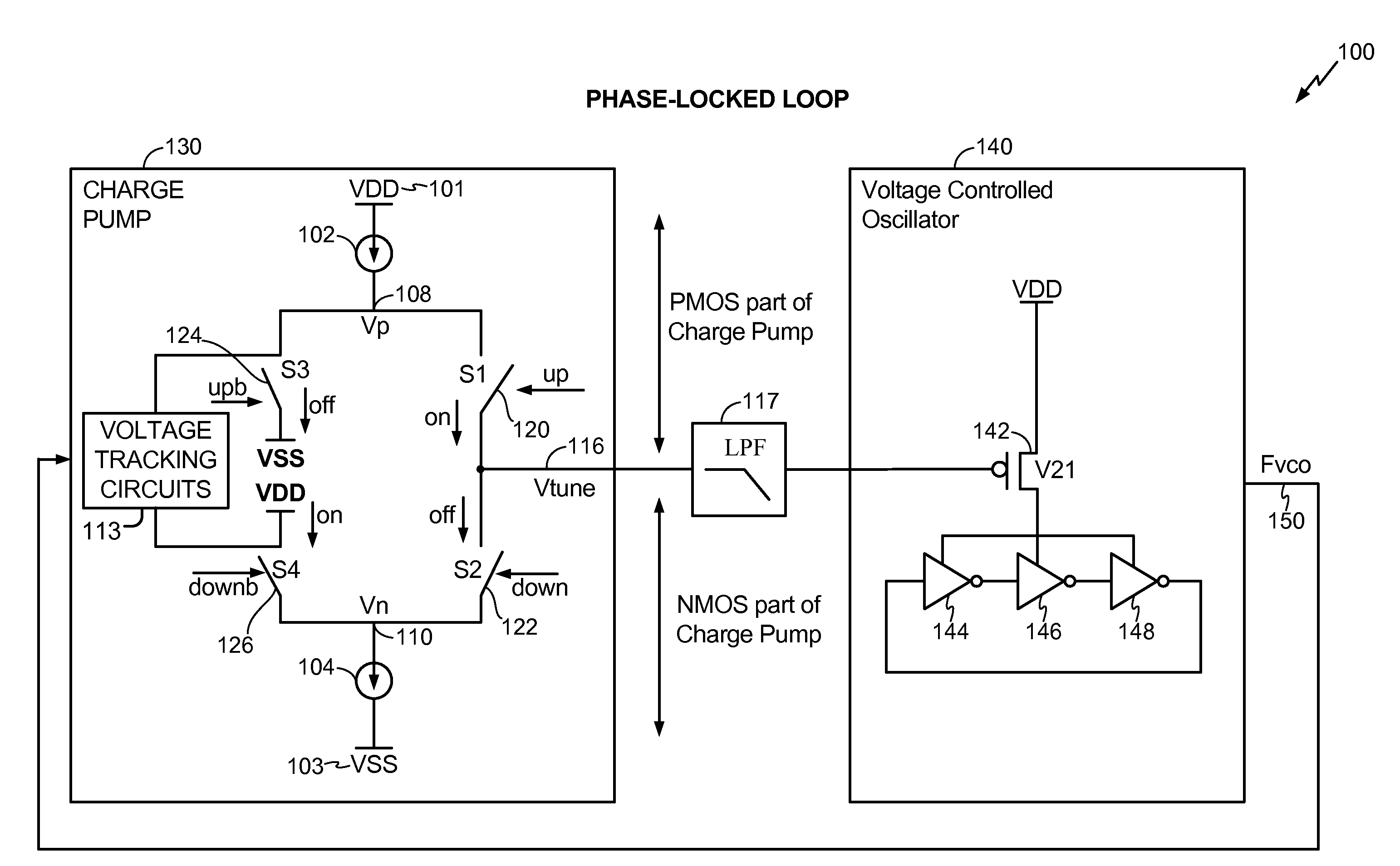
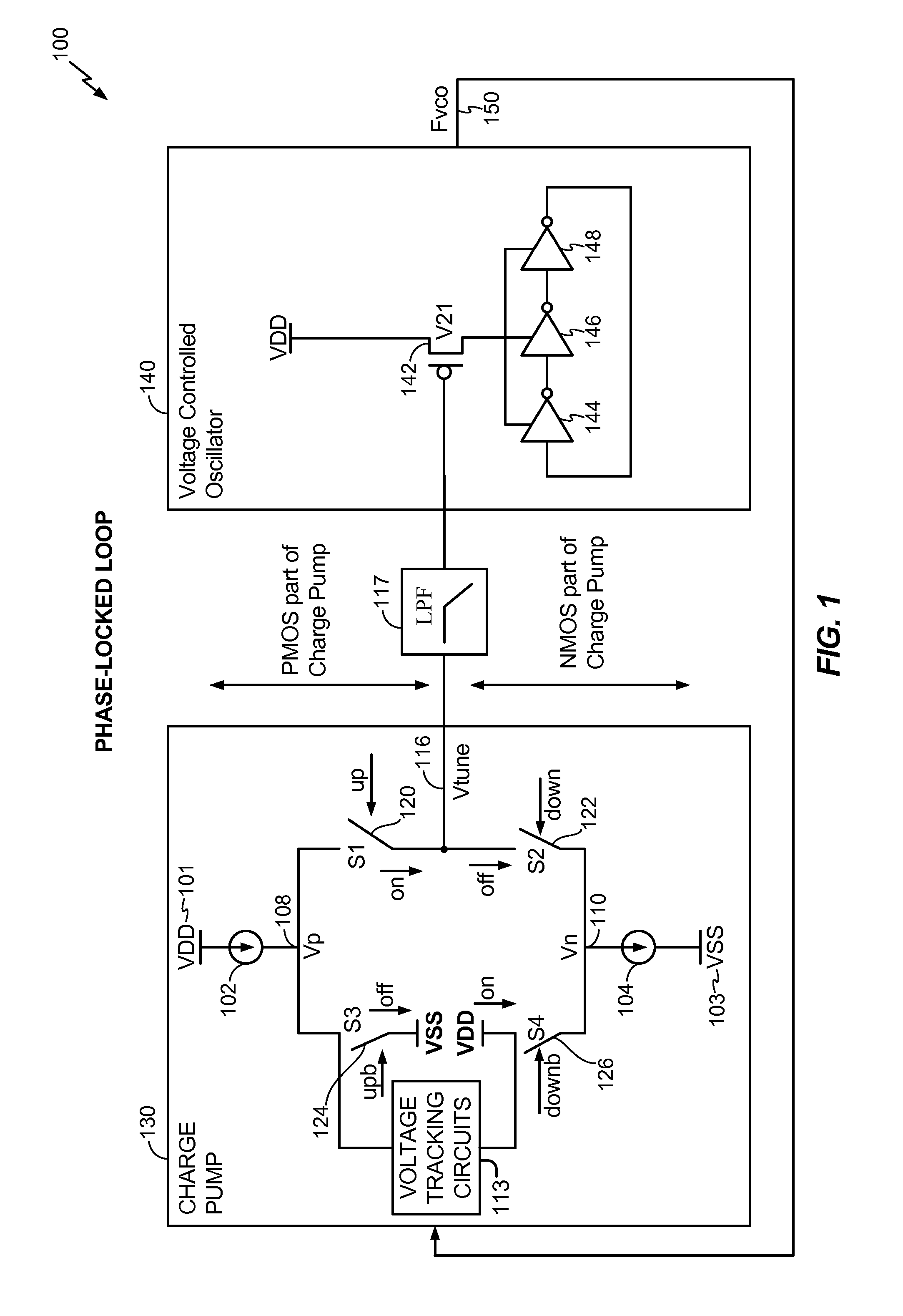
[0015]Referring to FIG. 1, a particular embodiment of a phase-locked loop 100 is shown. The phase-locked loop 100 includes a charge pump 130 coupled to a voltage controlled oscillator (VCO) 140. An output (Fvco) 150 of the voltage controlled oscillator 140 is provided to an input of the charge pump 130, forming a feedback path. The charge pump 130 has a PMOS portion and an NMOS portion. The charge pump 130 may be configured to generate a tuning voltage (Vtune) 116. The tuning voltage (Vtune) 116 is output by the charge pump 130 and is provided to the VCO 140 via a low pass loop filter 117. The voltage controlled oscillator 140 is responsive to the output of the low pass filter 117. The voltage controlled oscillator 140 is supplied by a voltage supply (VDD) and includes a transistor 142 and a plurality of serially coupled inverters 144, 146, and 148.

[0016]The charge pump 130 has a first voltage supply (VDD) 101 and a second voltage supply (VSS) 103. For example, the first voltage sup...


PUM


Abstract

A method includes tracking a tuning voltage at a first circuit coupled to a first drain node of a first supply of a charge pump. The method also includes tracking the tuning voltage at a second circuit coupled to a second drain node of a second supply of the charge pump. The method further includes stabilizing a first voltage of the first drain node and a second voltage of the second drain node responsive to the tuning voltage.

Description

I. FIELD[0001]The present disclosure is generally related to stabilizing charge pump node voltage levels.II. DESCRIPTION OF RELATED ART[0002]Advances in technology have resulted in smaller and more powerful computing devices. For example, there currently exist a variety of portable personal computing devices, including wireless computing devices, such as portable wireless telephones, personal digital assistants (PDAs), and paging devices that are small, lightweight, and easily carried by users. More specifically, portable wireless telephones, such as cellular telephones and Internet protocol (IP) telephones, can communicate voice and data packets over wireless networks. Further, many such wireless telephones include other types of devices that are incorporated therein. For example, a wireless telephone can also include a digital still camera, a digital video camera, a digital recorder, and an audio file player. Also, such wireless telephones can process executable instructions, incl...

Claims


Application Information

Patent Timeline
Patent Type & Authority Applications(United States)
IPC IPC(8): H03L7/06
CPCH03L7/0893
Inventor ZHONG, CHENGNAVUBOTHU, SWARNA L.DANG, NAM V.KONG, XIAOHUA
Owner QUALCOMM INC
Why Eureka
Try Eureka