
Fall detection using sensor fusion

Active Publication Date: 2013-05-16
VITAL CONNECT
View PDF4 Cites 72 Cited by
  • Summary
  • Abstract
  • Description
  • Claims
  • Application Information

AI Technical Summary

Benefits of technology

The patent is about a method and system for detecting falls using a combination of accelerometers and sensors. When an acceleration threshold is met, the method checks if there is a significant difference in height before and after the impact of the fall, and if there is a specific angle between the acceleration vector and the calibration vector. The system includes a processing system and an application that performs a similar analysis. The technical effect of the patent is that it provides a more accurate and reliable means for detecting falls, which can be useful in various applications such as sports equipment, safety devices, and eldercare monitoring.

Problems solved by technology

However, these conventional approaches fail to discriminate problematic falls from activities of daily living, such as falling onto a couch to take a nap, and require that the wireless sensor device be attached to the user in specific orientations.
These issues limit the fall detection capabilities of wireless sensor devices.

Method used


Image

  • Fall detection using sensor fusion
  • Fall detection using sensor fusion
  • Fall detection using sensor fusion

Examples


first embodiment

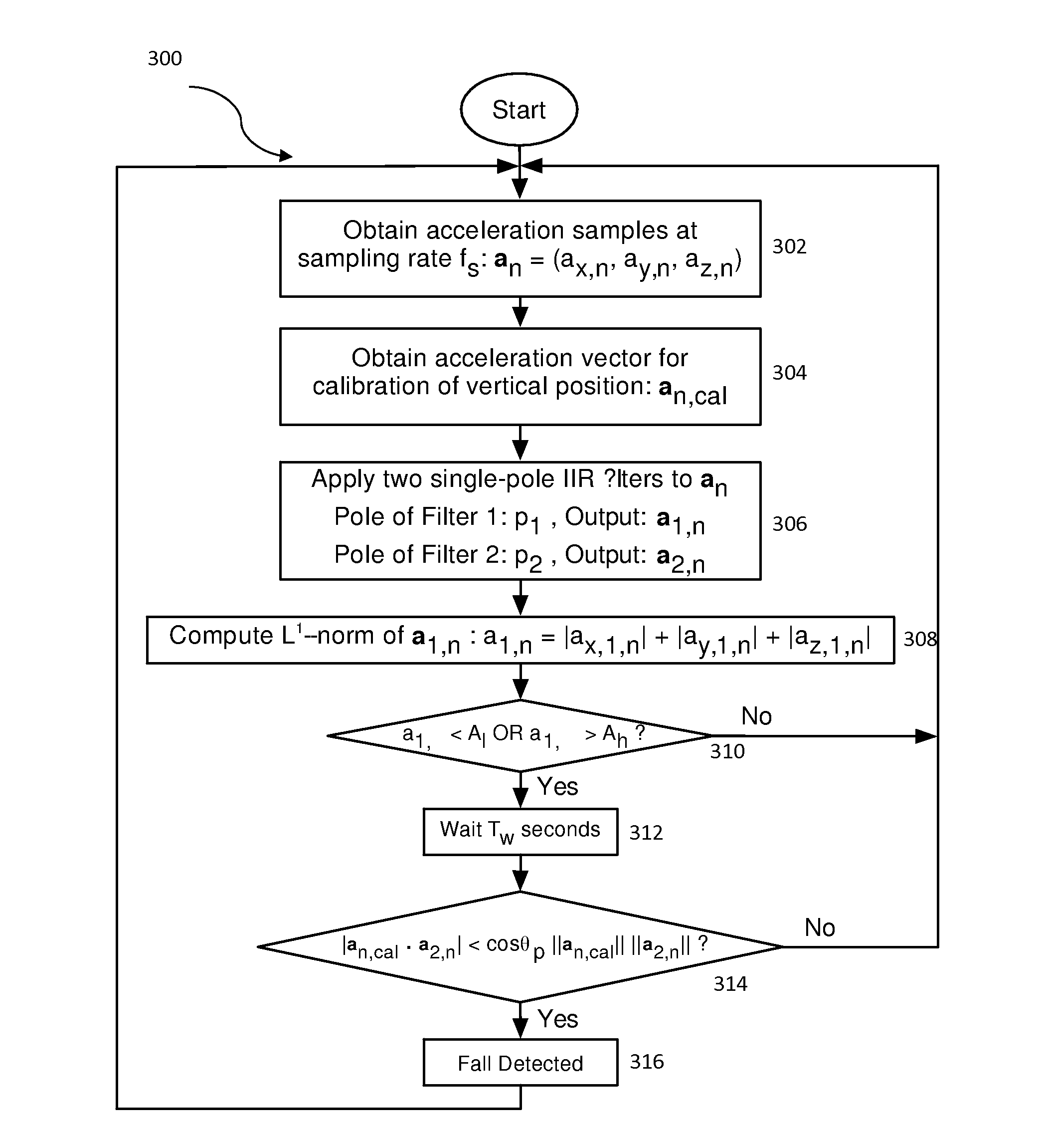
[0029]FIG. 3 illustrates a more detailed flowchart 300 of a method for fall detection in accordance with a In this embodiment, acceleration samples (an) are obtained from a user of the wireless sensor device 100 at a sampling rate (fs), via step 302. One of ordinary skill in the art readily recognizes that a variety of acceleration sample ranges can be utilized including but not limited to +−4 gravitational acceleration (g) and that would be within the spirit and scope of the present invention. In addition, one of ordinary skill in the art readily recognizes that a variety of sampling rates (fs) can be utilized including but not limited to 60 Hertz (Hz), 100 Hz, and 500 Hz and that would be within the spirit and scope of the present invention. The acceleration samples (an) can be represented by the following equation:

an=(ax,n,ay,n,az,n).  (1)

[0030]After obtaining the acceleration samples (an), an acceleration vector (an,cal) is obtained for the calibration of the vector position, v...

second embodiment

[0037]In one embodiment, the L1-norm computation of the output vector a1,n that results in a scalar a1,n is compared to both a lower acceleration magnitude threshold (Al) and also to a higher acceleration magnitude threshold (Ah). FIG. 4 illustrates a more detailed flowchart 400 of a method for fall detection in accordance with a Referring to FIG. 3 and FIG. 4 together, steps 402-408, which are similar to steps 302-308, are performed. After steps 402-408 are performed, scalar a1,n1 is compared to a lower acceleration magnitude threshold (Al), via step 410. If the condition in step 410, a1,n1l, is not satisfied, then additional acceleration samples (an) are obtained, via step 302.

[0038]If the condition in step 410 is satisfied, scalar a1,n2 is compared to a higher acceleration magnitude threshold (Ah) within a predetermined sampling number (Nw), via step 412. One of ordinary skill in the art readily recognizes that the predetermined sampling number (Nw) could include a varying numbe...


PUM


Abstract

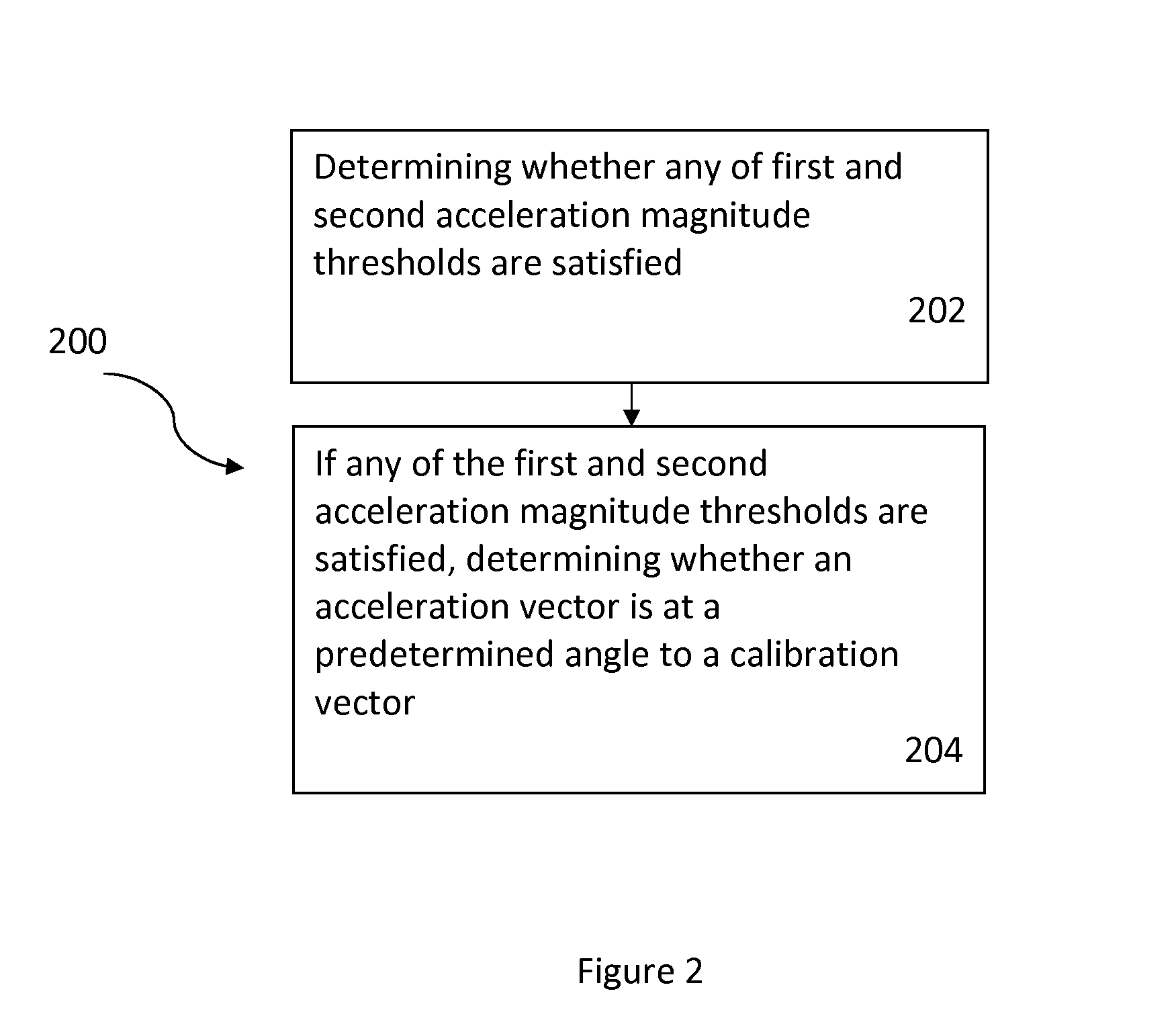
A method and system for fall detection using sensor fusion are disclosed. In a first aspect, the method comprises in response to any of first and second acceleration magnitude thresholds being satisfied, determining whether a height difference before and after impact of a fall satisfies a threshold and whether an angle threshold between an acceleration vector and a calibration vector is satisfied. In a second aspect, the system comprises a processing system and an application coupled to the processing system, wherein the application carries out the steps of the method.

Description

CROSS-REFERENCE TO RELATED APPLICATION[0001]This application is a continuation-in-part of U.S. patent application Ser. No. 13 / 296,139, filed Nov. 14, 2011, entitled “METHOD AND SYSTEM FOR FALL DETECTION OF A USER,” which is incorporated herein by reference in its entirety.FIELD OF THE INVENTION[0002]The present invention relates to wireless sensor devices, and more particularly, to using a wireless sensor device to detect a user's fall.BACKGROUND[0003]Wireless sensor devices are used in a variety of applications including the health monitoring of users. In many of these health monitoring applications, a wireless sensor device is attached directly to the user's skin to measure certain data. This measured data can then be utilized for a variety of health related applications. In one instance, this measured data can be utilized to assist in detecting when a user has fallen due to a health related disease or external factor and is injured as a result.[0004]Conventional approaches have d...

Claims


Application Information

Patent Timeline
IPC IPC(8): G01P15/00G08B21/02
CPCG01P15/00G08B21/02A61B5/1117A61B5/725G08B21/043G08B21/0446G01P15/0891
Inventor NARASIMHAN, RAVIFERDOSI, NIMACHAN, ALEXANDER
Owner VITAL CONNECT
Learn More