
Wall Wash Lighting Fixture

Inactive Publication Date: 2013-05-16
ELECTRIX
View PDF6 Cites 21 Cited by
  • Summary
  • Abstract
  • Description
  • Claims
  • Application Information

AI Technical Summary

Benefits of technology

The patent describes a way to make a light fixture that can wash or graze a wall well. This is done by using LEDs that emit light in a specific way. By having a specifically designed optic, the light is distributed more evenly and the fixture is more compact. This design can improve the appearance of the lighting and make it more efficient.

Problems solved by technology

In such fixtures, much light is wasted.
Additionally, there is often an uneven pattern with a harsh high illumination region near the fixture.

Method used


Image

  • Wall Wash Lighting Fixture
  • Wall Wash Lighting Fixture
  • Wall Wash Lighting Fixture

Examples


Embodiment Construction

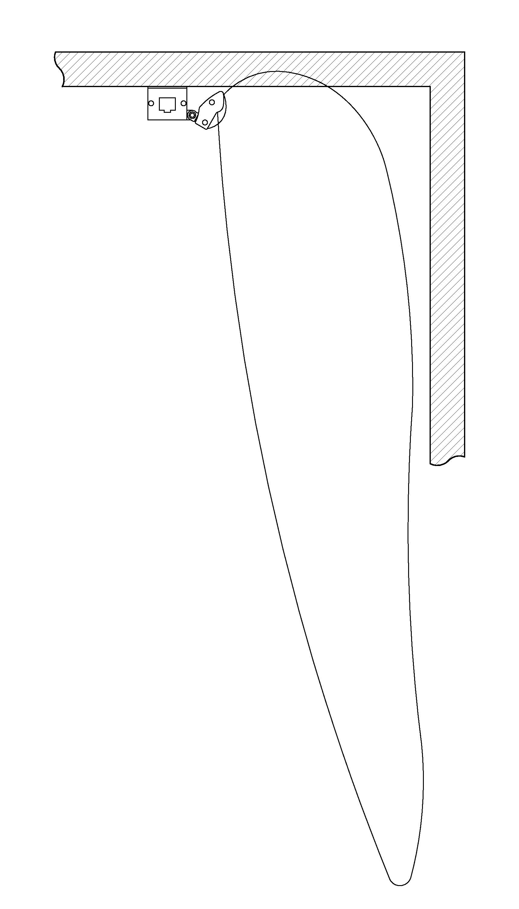
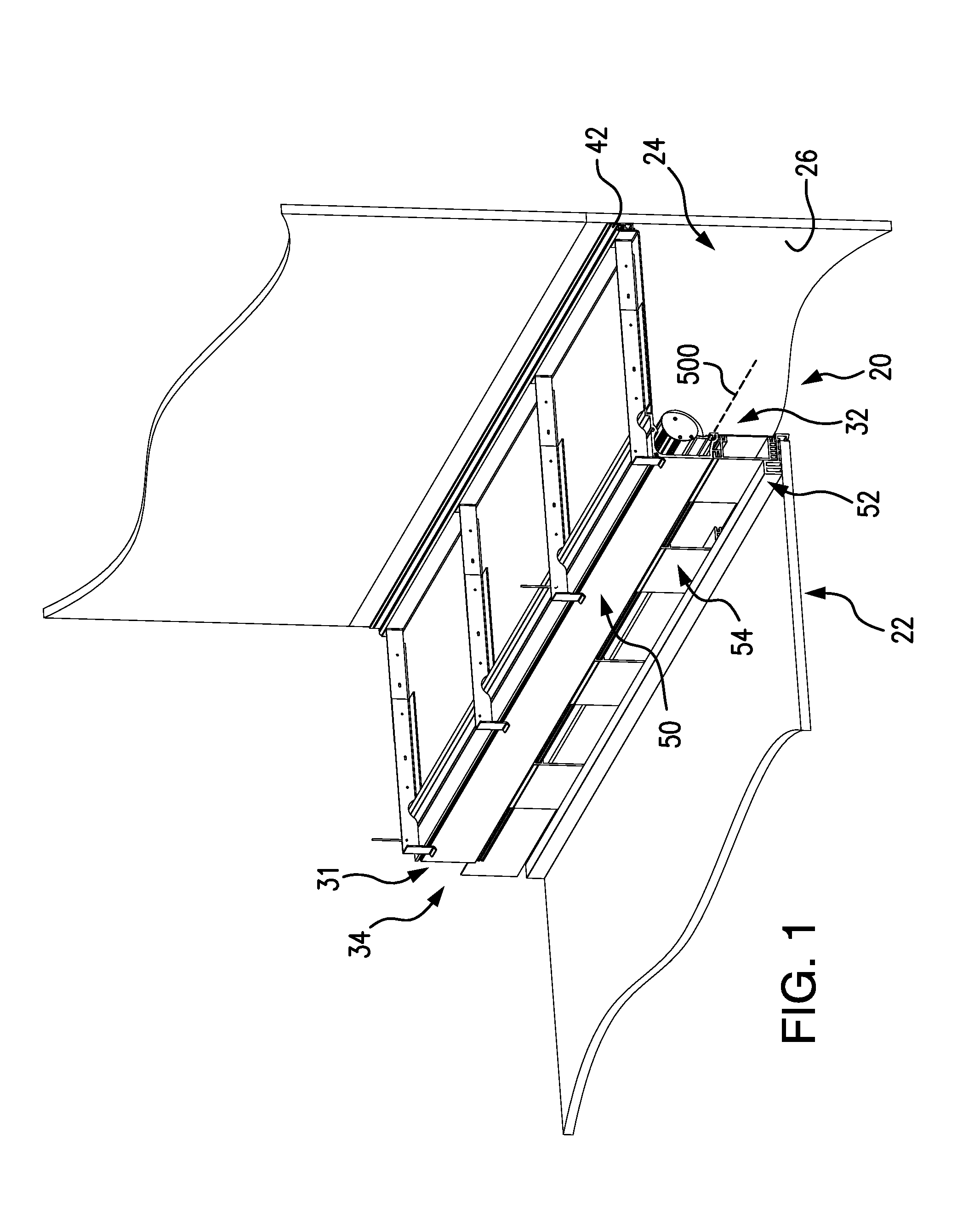
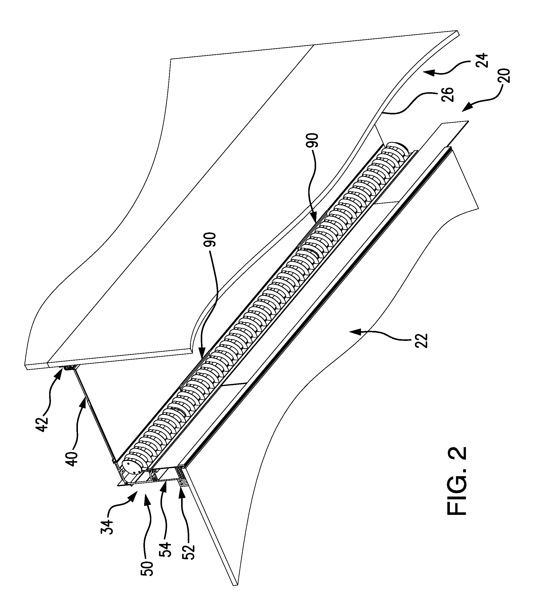
[0057]FIGS. 1-3 show a fixture 20 recessed in a ceiling 22 along the junction of that ceiling with a wall 24. The wall 24 has a surface 26 extending downward to a surface 28 (FIG. 3) of a floor structure 30. The fixture extends from a first end 31 to a second end 32.

[0058]The fixture is secured via mounting brackets 40 (e.g., stamped cold rolled steel (CRS)) to the wall. The exemplary brackets 40 are, themselves, secured to the wall via an elongate wall bracket 42 (e.g., extruded aluminum alloy) secured to the wall (e.g., screwed). In the exemplary implementation, a downward facing hook at the wall end of the bracket 40 mates with an upward facing hook of the bracket extrusion 42 to support the bracket 40 near the wall. At the opposite end of the bracket 40, the bracket 40 may be suspended by a guy wire 43 from a structural ceiling, beam, or the like.

[0059]A fixture body 34 is mounted to the brackets. The exemplary fixture body may, in turn, locally support or be otherwise secured t...


PUM

PropertyMeasurementUnit
Distributionaaaaaaaaaa

Abstract

A light fixture has a body and a plurality of light emitting diodes. A carrier supports the light emitting diodes and is pivotally mounted to the body. An asymmetric lens is mounted to the carrier.

Description

CROSS-REFERENCE TO RELATED APPLICATIONS[0001]Benefit is claimed of U.S. Patent Applications Ser. Nos. 61 / 558,072 and 61 / 673,947, filed Nov. 10, 2011 and Jul. 20, 2012, and entitled “Wall Wash Lighting Fixture”, the disclosures of which are incorporated by reference herein in their entireties as if set forth at length.BACKGROUND OF THE INVENTION[0002]The invention relates to architectural lighting. More particularly, the invention relates to a wall wash lighting fixture.[0003]In architectural lighting, it is often desired to wash a wall with light. Light fixtures are located in the ceiling near the wall and positioned to direct light downward along the wall (grazing the wall). In such fixtures, much light is wasted. Additionally, there is often an uneven pattern with a harsh high illumination region near the fixture.[0004]Linear LED wall wash lighting fixtures have been recently proposed.SUMMARY OF THE INVENTION[0005]The directionality and compactness of light emitting diodes (LEDs) ...

Claims


Application Information

Patent Timeline
IPC IPC(8): F21S4/00F21S8/02B23P11/00F21V5/04
CPCF21V33/006F21S8/037F21V3/0436Y10T29/49826F21W2131/1005F21Y2103/003F21V5/08F21Y2103/10F21Y2115/10F21V3/062
Inventor SWISHA, GORDON L.LOMENZO, JOSEPH J.AIKENS, DAVID M.
Owner ELECTRIX
Learn More