Hydrodynamic bearing assembly and spindle motor including the same

a technology of bearing assembly and spindle motor, which is applied in the direction of sliding contact bearings, mechanical equipment, mechanical energy handling, etc., can solve the problems of increased variation in oil interface, ineffective formation of journal bearings, and excessive amount of oil, so as to improve bearing rigidity

Inactive Publication Date: 2013-05-16
SAMSUNG ELECTRO MECHANICS CO LTD
View PDF2 Cites 6 Cited by
  • Summary
  • Abstract
  • Description
  • Claims
  • Application Information

AI Technical Summary

Benefits of technology

[0012]An aspect of the present invention provides a spindle motor having improved bearing rigidity even in the case of a sintered sleeve being used therein.

Problems solved by technology

However, when the sintered sleeve is used, it may have an excessive amount of oil, such that a variation in an oil interface is increased due to the thermal expansion of the oil.
In the hydrodynamic bearing assembly using this sintered sleeve, since a number of pores are present in an inner peripheral surface of the sintered sleeve, a large amount of oil in a bearing clearance formed between the shaft and the sleeve may be absorbed at the time of an operation of the motor, such that a journal bearing may not be effectively formed.

Method used


Image

  • Hydrodynamic bearing assembly and spindle motor including the same
  • Hydrodynamic bearing assembly and spindle motor including the same
  • Hydrodynamic bearing assembly and spindle motor including the same

Examples


first embodiment

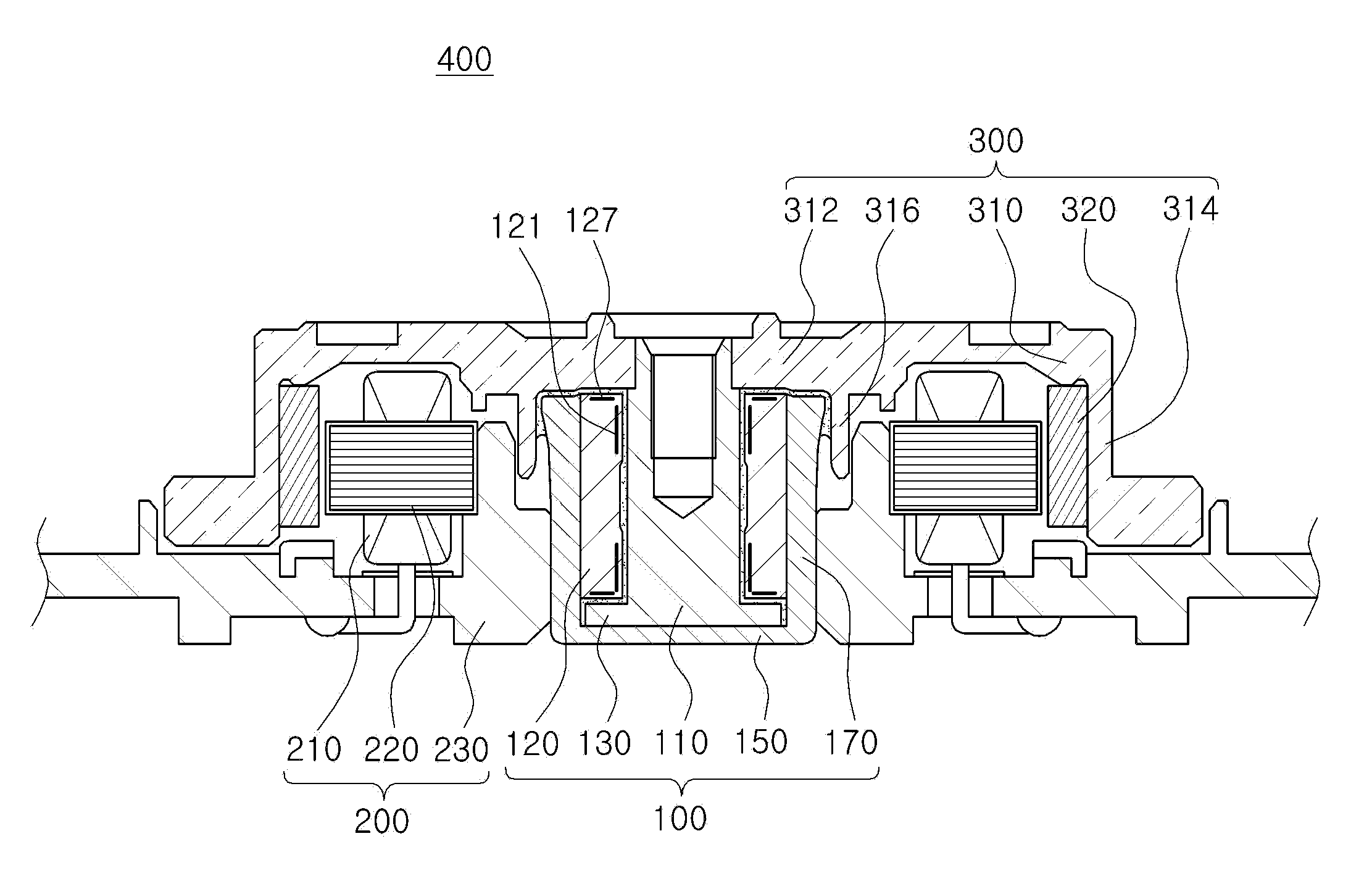
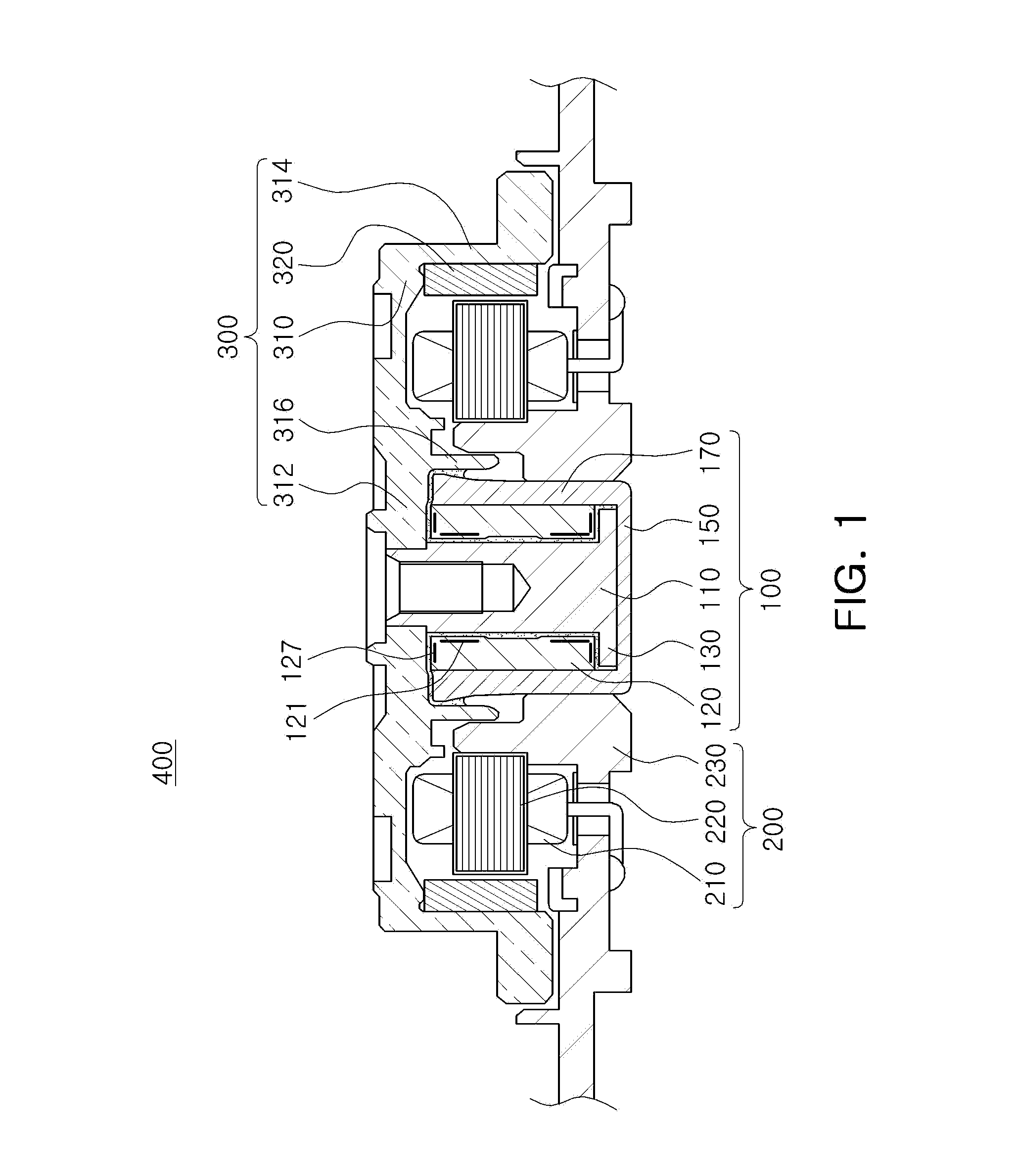
[0030]Referring to FIGS. 1 through 3, a spindle motor 400 according to the present invention may include a hydrodynamic bearing assembly 100, a stator 200, and a rotor 300.

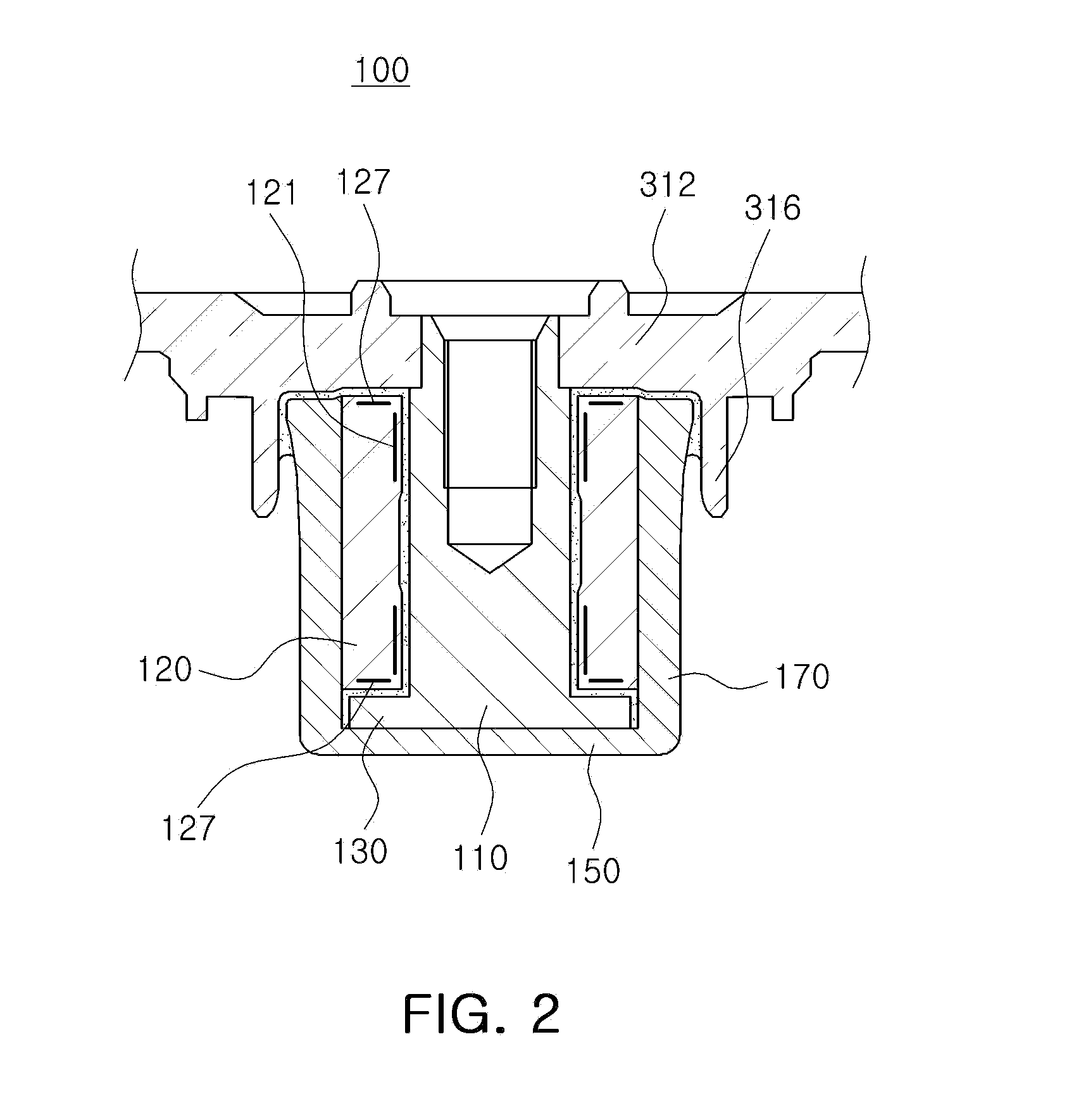
[0031]The hydrodynamic bearing assembly 100 may include a shaft 110, a sleeve 120, a thrust plate 130, a cover member 140, and a housing 170.

[0032]Here, terms with respect to directions will be first defined. As viewed in FIGS. 1 and 2, an axial direction refers to a vertical direction based on the shaft 110 and an outer diameter direction or an inner diameter direction refers to a direction toward an outer edge of the rotor 300 based on the shaft 110 or a direction toward the center of the shaft 110 based on the outer edge of the rotor 300.

[0033]The sleeve 120 may support the shaft 110 such that an upper end of the shaft 110 protrudes upwardly in the axial direction. The sleeve 120 may be formed by sintering a Cu—Fe-based alloy powder or a steel use stainless (SUS)-based powder.

[0034]Here, the shaft 110 may be in...

second embodiment

[0068]The hydrodynamic bearing assembly 100′ according to the present invention may include the shaft 110, the sleeve 120, a thrust plate 130′, a cap member 140′, the cover member 150, and the housing 170.

[0069]Here, terms with respect to directions will be first defined. As viewed in FIGS. 4 and 5, an axial direction refers to a vertical direction based on the shaft 110 and an outer diameter direction or an inner diameter direction refers to a direction toward an outer edge of the rotor 300 based on the shaft 110 or a direction toward the center of the shaft 110 based on the outer edge of the rotor 300.

[0070]The sleeve 120 may support the shaft 110 such that the upper end of the shaft 110 protrudes upwardly in the axial direction. The sleeve 120 may be formed by sintering a Cu—Fe-based alloy powder or a SUS-based powder.

[0071]Here, the shaft 110 may be inserted into the shaft hole 122 of the sleeve 120 such that the shaft 110 and the sleeve 120 have the micro clearance therebetween...


PUM


Abstract

The hydrodynamic bearing assembly includes: a sintered sleeve having a shaft hole formed therein such that a shaft is rotatably inserted thereinto and including at least one dynamic pressure bearing part to generate dynamic pressure in a lubricating fluid filled in a bearing clearance at the time of rotation of the shaft; and a housing provided to enclose an outer peripheral surface of the sintered sleeve, wherein a bottom surface of a dynamic pressure groove of the at least one dynamic pressure bearing part has a porosity higher than that of a protrusion surface thereof.

Description

CROSS-REFERENCE TO RELATED APPLICATIONS[0001]This application claims the priority of Korean Patent Application No. 10-2011-0116975 filed on Nov. 10, 2011, in the Korean Intellectual Property Office, the disclosure of which is incorporated herein by reference.BACKGROUND OF THE INVENTION[0002]1. Field of the Invention[0003]The present invention relates to a hydrodynamic bearing assembly and a spindle motor including the same.[0004]2. Description of the Related Art[0005]A hard disk drive (HDD), an information storage device, reads data stored on a disk or writes data to the disk using a read / write head.[0006]The hard disk drive requires a disk driving device capable of driving the disk. As the disk driving device, a small-sized motor is used.[0007]In the small-sized motor, a hydrodynamic bearing assembly is commonly used. A shaft, a rotating member of the hydrodynamic bearing assembly, and a sleeve, a fixed member thereof, include oil interposed therebetween, such that the shaft is sup...

Claims


Application Information

Patent Timeline
Patent Type & Authority Applications(United States)
IPC IPC(8): H02K7/08
CPCH02K7/08H02K5/1675F16C33/128F16C33/107F16C17/107F16C33/145
Inventor JUN, CHANG KEUN
Owner SAMSUNG ELECTRO MECHANICS CO LTD
Why Eureka
Try Eureka