Method for storing compressed air in porous subsurface locations

a technology of porous subsurface and compressed air, which is applied in the direction of storage devices, mining structures, machines/engines, etc., can solve the problems of limited quantity of subterranean salt caverns and physical locations of such subterranean salt caverns not always proxima

Inactive Publication Date: 2013-05-16
CONOCOPHILLIPS CO
View PDF8 Cites 6 Cited by
  • Summary
  • Abstract
  • Description
  • Claims
  • Application Information

AI Technical Summary

Benefits of technology

[0006]In yet another embodiment, a process for storing compressed air in a porous subterranean formation, having steps in the following order, includes: placing an air injection tube at a peak of the porous subterranean formation; without injecting air into the porous subterranean formation, lowering an internal pressure of the porous subterranean formation to a first predetermined pressure by pumping water from the porous subterranean formation to an earthen surface; simultaneously injecting air into the porous subterranean formation via the air injection tube and pumping water from the porous subterranean formation; measuring the internal pressure of the porous subterranean formation; increasing an air injection rate into the porous subterranean formation upon the internal pressure reaching the first predetermined pressure; and creating and maintaining a volume of compressed air at the peak of the porous subterranean formation by cycling between injecting air into the porous subterranean formation producing air from the porous subterranean formation.

Problems solved by technology

One drawback of using subterranean salt caverns is that the quantity of such subterranean salt caverns is limited.
Another drawback of using subterranean salt caverns is that the physical locations of such subterranean salt caverns are not always proximate a commercially available electrical energy source.

Method used


Image

  • Method for storing compressed air in porous subsurface locations
  • Method for storing compressed air in porous subsurface locations
  • Method for storing compressed air in porous subsurface locations

Examples


Embodiment Construction

[0016]Turning to FIGS. 1-8 a detailed description of the preferred arrangements of the present disclosure will be provided. While various embodiments are described and illustrated, the scope of the disclosure is not intended to be limited by such description and illustrations, but only by the scope of the claims that follow.

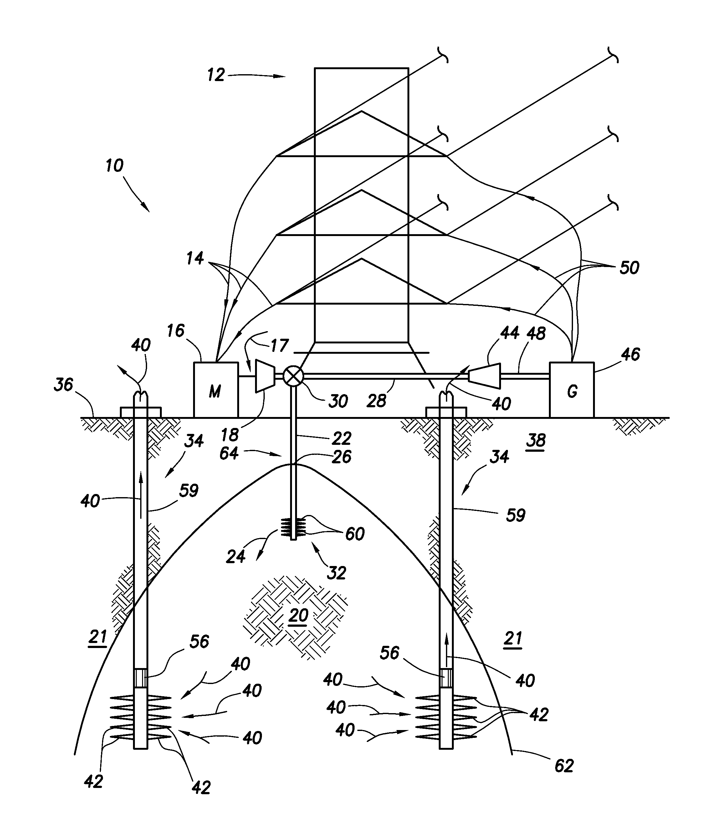
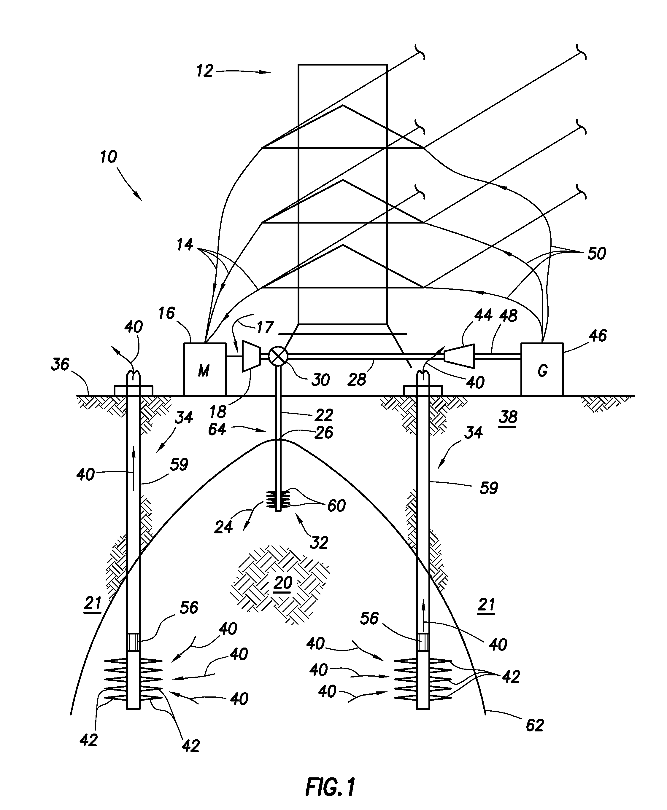
[0017]Compressed Air Energy Storage (CAES) utilizes off-peak electrical energy as a first energy form to generate and store a second energy form, which may be used at a later time to generate electrical energy when electrical energy demand is relatively high and more expensive than the cost of off-peak electrical energy. With reference to FIG. 1, a CAES system 10 may utilize an electrical power line 12 from which electrical energy may be supplied through one or more electrical down wires 14 to a motor 16. Electricity may be diverted or utilized from a power grid, which power line 12 may be part of and integrally linked. Motor 16 may utilize electricity from power...


PUM


Abstract

A methodology for storing compressed air in porous subterranean formations for subsequent production and use in generating electricity.

Description

CROSS-REFERENCE TO RELATED APPLICATIONS[0001]This application claims priority benefit under 35 U.S.C. Section 119(e) to U.S. Provisional Patent Ser. No. 61 / 560,017 filed on Nov. 15, 2011, the entire disclosure of which is incorporated herein by reference.FIELD OF THE INVENTION[0002]This invention relates to a methodology for storing compressed air in porous subterranean formations for subsequent production and use in generating electricity.BACKGROUND OF THE INVENTION[0003]Compressed Air Energy Storage (CAES) is a technique employing an available off-peak energy supply and converting it to a secondary form of energy, such as compressed air, and then employing that second form of energy during periods of peak electrical energy demand to generate electricity. In one example, off-peak electrical energy from a common commercial electrical energy grid may be used to operate an air compressor to compress air and direct the compressed air to subterranean salt caverns for storage. After a pe...

Claims


Application Information

Patent Timeline
Patent Type & Authority Applications(United States)
IPC IPC(8): B65G5/00
CPCY02E60/15F02C6/16Y02E60/16B65G5/00B65G5/005
Inventor BERNICA, JOSEPH G.SYLTE, JAMES E.
Owner CONOCOPHILLIPS CO
Why Eureka
Try Eureka