Insulator with Air Dielectric Cavities for Electrical Connector

a dielectric cavity and air technology, applied in the direction of coupling device connection, coupling protective earth/shielding arrangement, securing/insulating coupling contact member, etc., can solve the problems of reducing the effective dielectric constant of materials, totally unacceptable in most applications, etc., to reduce crosstalk, reduce the effective dielectric constant, and preserve signal fidelity

Active Publication Date: 2013-05-16
AIRBORN
View PDF13 Cites 8 Cited by
  • Summary
  • Abstract
  • Description
  • Claims
  • Application Information

AI Technical Summary

Benefits of technology

[0006]The present invention is an insulator with air dielectric cavities for an electrical connector. The air dielectric cavities help reduce the effective dielectric constant of the materials used to construct the insulator. The reduction of the effective dielectric constant allows for the transmission of high-speed signals while maintaining impedance, thereby preserving signal fidelity. Air dielectric cavities are disposed in an alternating configuration between contact cavities. The contact cavities and air dielectric cavities can be arranged in rows where the spacing of each row is offset to reduce crosstalk. Data pair cavities and sideband cavities are separated to also reduce crosstalk.

Problems solved by technology

Even if the impedance of the power supply circuit were only 0.10 ohms, the voltage drop in this example would be 0.5 volts (5 amps times 0.1 ohm), which would be totally unacceptable in most applications.
The air dielectric cavities help reduce the effective dielectric constant of the materials used to construct the insulator.

Method used


Image

  • Insulator with Air Dielectric Cavities for Electrical Connector
  • Insulator with Air Dielectric Cavities for Electrical Connector
  • Insulator with Air Dielectric Cavities for Electrical Connector

Examples


Embodiment Construction

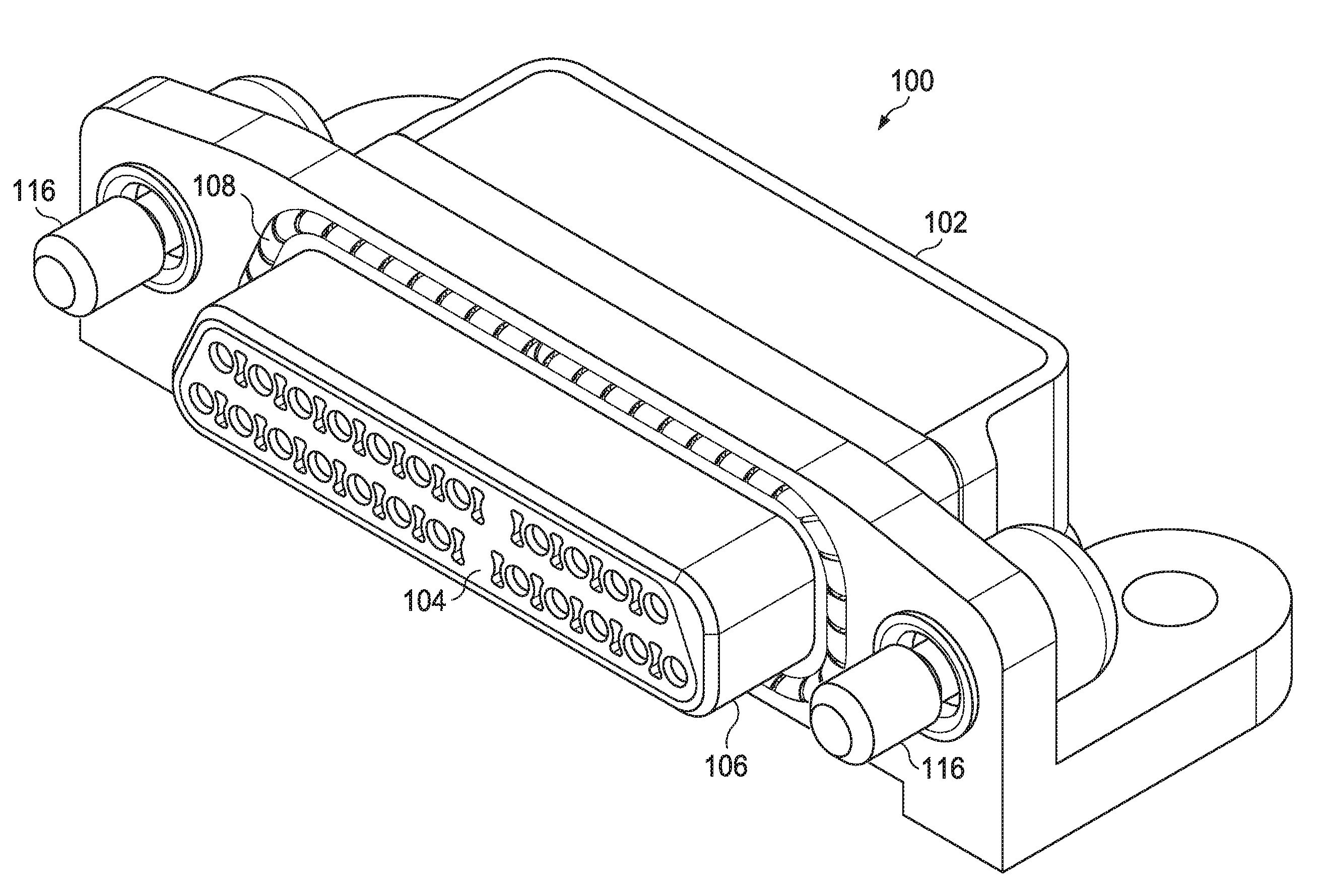
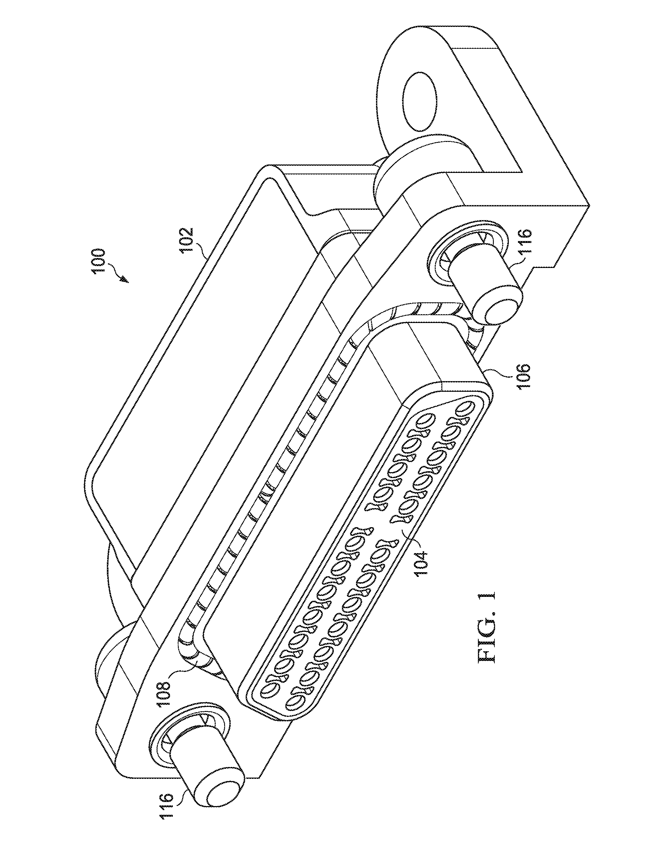
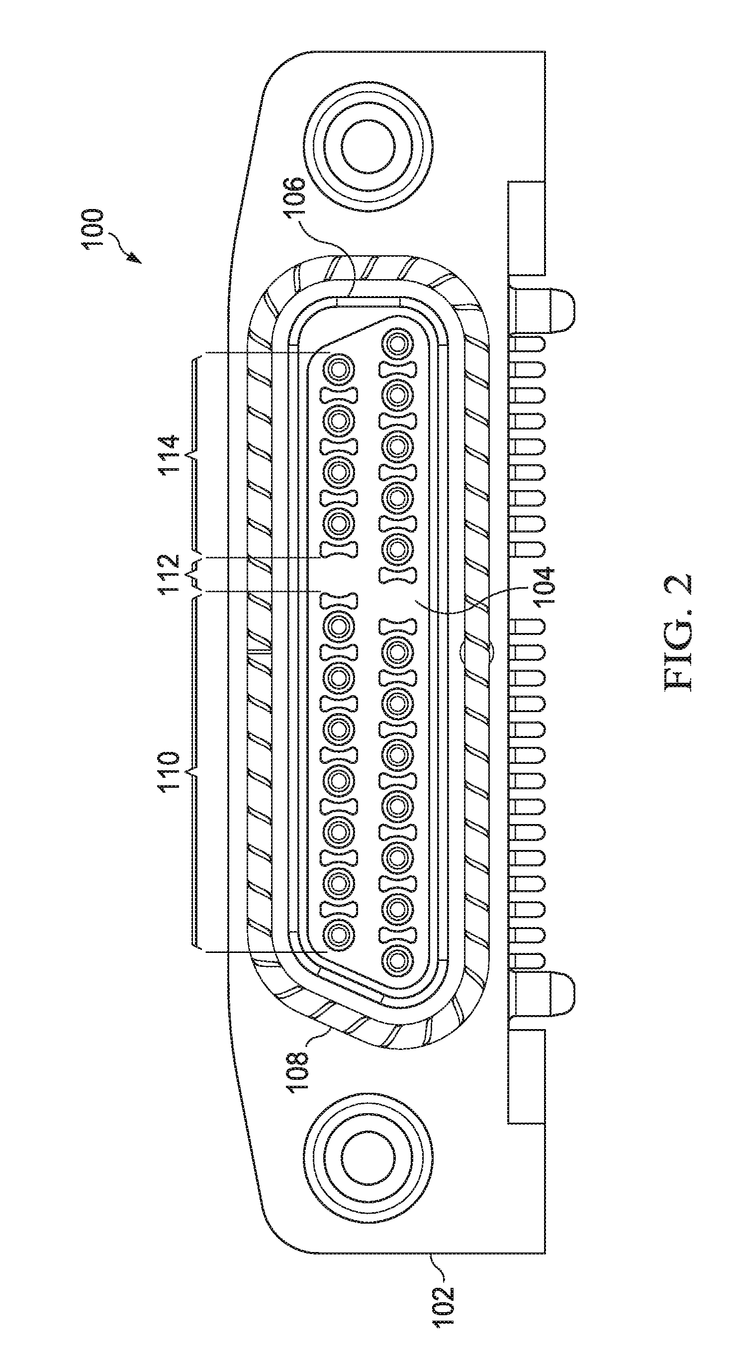
[0016]As shown in at least FIGS. 1 and 5-7, a connector 100 comprises a back shell 102, an insulator 104, a metal shell 106, and an electro-magnetic insulating (“EMI”) band 108. Connector 100 can be either a male or female cable, vertical, right-angle, edge-mounted, or straddle-mounted connector. FIG. 1 depicts an example of a right-angle male connector. FIG. 7 depicts an example of a right-angle female connector. FIG. 8 depicts an example of a vertical male connector. As shown in FIG. 1, metal shell 106 is disposed within the front of back shell 102. Insulator 104 is desirably encased in metal shell 106. EMI band 108 is disposed on the front face of back shell 102 and traces the outside perimeter of metal shell 106. EMI band 108 provides insulation against electro-magnetic interference. Insulator 104 can be made of any suitable material for electrical connectors, preferably a durable plastic. As shown in FIGS. 5 and 6, insulator 104 has a front surface 104A and a back surface 104B....


PUM


Abstract

An insulator for an electrical connector that comprises a back shell, metal shell, EMI band, and the insulator. The insulator features alternating contact cavities and air dielectric cavities. The air dielectric cavities reduce the effective dielectric constant of the connector, which allows high-speed data to be transmitted while maintaining impedance, thereby preserving signal fidelity.

Description

BACKGROUND OF THE INVENTION[0001]1. Field of Invention[0002]The present invention is directed to an insulator for an electrical connector having air cavities between contact cavities to reduce the effective dielectric constant of the material used to construct the insulator, which allows for a tighter contact pitch.[0003]2. Description of Related Art[0004]Prior connectors have featured air channels or passages. Connectors with air channels or passages are mentioned, for example, in U.S. Pat. No. 6,814,590; U.S. Pat. No. 7,303,427; U.S. 2007 / 0293084; and U.S. 2010 / 0330846. In contrast to the air cavities of the present invention, however, the air channels or passages in other connectors perform a completely different function. In these other connectors, the connector contacts are intended to carry a high current, not high-speed digital data. In connectors that carry a high current, the purpose of the air channels is to allow airflow within the connector for the purposes of dissipatin...

Claims


Application Information

Patent Timeline
Patent Type & Authority Applications(United States)
IPC IPC(8): H01R13/648H01R24/00H01R13/46
CPCH01R12/724H01R13/6584H01R13/6477
Inventor SOUBH, EMADTRAUGOTT, KEVIN
Owner AIRBORN
Why Eureka
Try Eureka