Antenna module, communication device, and array antenna

a technology of array antennas and antenna modules, applied in the direction of individual energised antenna arrays, radiating element structures, radiating element housings, etc., can solve the problem of narrow frequency band width of antennas

Pending Publication Date: 2021-06-17
MURATA MFG CO LTD
View PDF0 Cites 1 Cited by
  • Summary
  • Abstract
  • Description
  • Claims
  • Application Information

AI Technical Summary

Benefits of technology

[0005]For the above antenna, permittivity of a dielectric substrate on which antenna elements (radiation electrodes) are implemented has an effect on its antenna characteristics, such as a frequency band width, a peak gain, and a loss of a transmittable radio-frequency signal. Among them, the frequency band width typically increases with the increase in the thickness of the dielectric substrate (that is, the distance between a radiation electrode and a ground electrode and the distance between radiation electrodes).

Problems solved by technology

If a dielectric substrate becomes thinner, however, an issue arises in that the frequency band width of the antenna becomes narrower.

Method used


Image

  • Antenna module, communication device, and array antenna
  • Antenna module, communication device, and array antenna
  • Antenna module, communication device, and array antenna

Examples


first embodiment

(Basic Configuration of Communication Device)

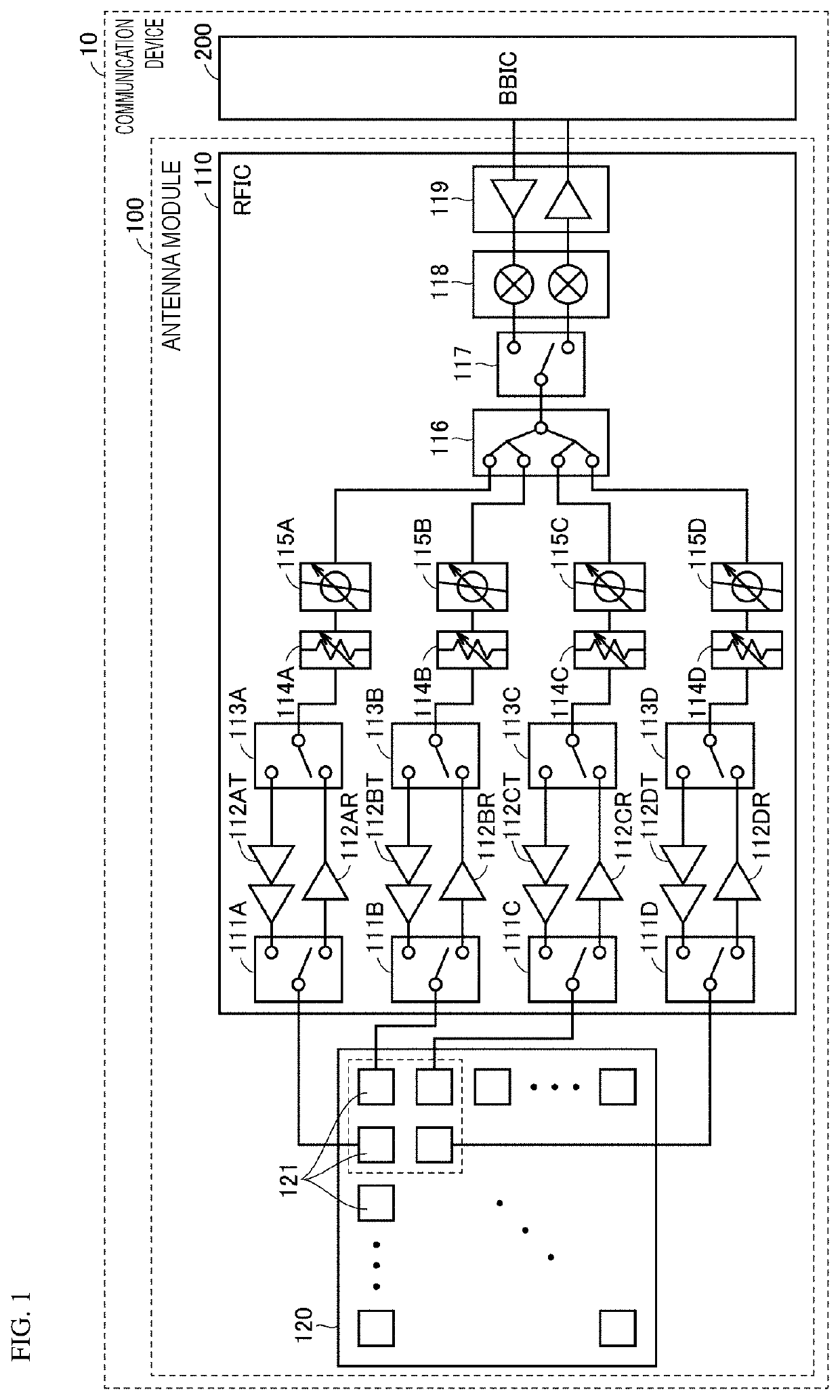
[0040]FIG. 1 is a block diagram of an example of a communication device 10 in which an antenna module 100 according to the present embodiment is used. Examples of the communication device 10 may include a mobile terminal, such as a cellular phone, a smartphone, or a tablet, and a personal computer having the communication function.

[0041]Referring to FIG. 1, the communication device 10 includes the antenna module 100 and a base band integrated circuit (BBIC) 200 constituting a baseband signal processing circuit. The antenna module 100 includes a radio frequency integrated circuit (RFIC) 110 being one example of a feeder circuit and an antenna array 120. The communication device 10 is configured to upconvert signals conveyed from the BBIC 200 to the antenna module 100 into radio-frequency signals and radiate them from the antenna array 120, and configured to downconvert radio-frequency signals received at the antenna array 120 and perform s...

second embodiment

[0086]In the first embodiment, the hollow portion 150 disposed inside the dielectric substrate 160 is basically an air layer.

[0087]In a second embodiment, an example in which the hollow portion 150 disposed between the two the radiation electrodes 121 and 122 is at least partially filled with another dielectric having permittivity lower than that of the dielectric substrate 160 is described.

[0088]FIG. 18 includes a plan view and a cross-sectional view of an antenna module 100H according to the second embodiment. The antenna module 100H is the one in which the hollow portion 150 and the cavity portion 152 in the antenna module 100 according to the first embodiment are filled with a dielectric material 170 having permittivity lower than that of the dielectric forming the dielectric substrate 160.

[0089]Because the hollow portion 150 is filled with the different dielectric material having the lower permittivity, the effective permittivity can be more reduced than that in the case where ...

third embodiment

[0092]The antenna module in the first embodiment has the configuration in which the two radiation electrodes are stacked. The number of radiation electrodes stacked may be three or more.

[0093]In a third embodiment and its variations, examples in which the same configuration as that of the first embodiment is applied to an antenna module including three stacked radiation electrodes are described.

[0094]FIG. 22 includes a plan view and a cross-sectional view of an antenna module 100L according to the third embodiment. The antenna module 100L in FIG. 22 further includes a radiation electrode 123 (third radiation electrode) being a parasitic element, in addition to the radiation electrode 121, which is a feed element, and the radiation electrode 122, which is a parasitic element.

[0095]The radiation electrode 123 is disposed on a layer between the radiation electrodes 121 and 122. In the example of the antenna module 100L, the radiation electrodes 122 and 123 have the same dimensions and ...


PUM

PropertyMeasurementUnit
frequencyaaaaaaaaaa
frequencyaaaaaaaaaa
frequencyaaaaaaaaaa

Abstract

An antenna module (100) includes a dielectric substrate (160) having a multilayer structure, a first radiation electrode (122), a second radiation electrode (121), and a ground electrode (GND). The second radiation electrode (121) is arranged between the first radiation electrode (122) and the ground electrode (GND) in a lamination direction of the dielectric substrate (160). In the dielectric substrate (160), a hollow portion (150) is disposed in at least a portion between the first radiation electrode (122) and the second radiation electrode (121).

Description

CROSS REFERENCE TO RELATED APPLICATION[0001]This is a continuation of International Application No. PCT / JP2019 / 035606 filed on Sep. 11, 2019 which claims priority from Japanese Patent Application No. 2018-182098 filed on Sep. 27, 2018. The contents of these applications are incorporated herein by reference in their entireties.BACKGROUND OF THE DISCLOSUREField of the Disclosure[0002]The present disclosure relates to an antenna module, a communication device, and an array antenna and more specifically to a technique for broadening the antenna module.Description of the Related Art[0003]International Publication No. 2016 / 063759 (Patent Document 1) discloses a patch antenna in which a plurality of radiation electrodes (feed elements, parasitic elements) having a planar shape are stacked.[0004]Patent Document 1: International Publication No. 2016 / 063759BRIEF SUMMARY OF THE DISCLOSURE[0005]For the above antenna, permittivity of a dielectric substrate on which antenna elements (radiation el...

Claims


Application Information

Patent Timeline
Patent Type & Authority Applications(United States)
IPC IPC(8): H01Q1/42H01Q13/18H01Q1/22H01Q21/06
CPCH01Q1/422H01Q21/065H01Q1/2283H01Q13/18H01Q1/38H01Q1/243
Inventor FURUHI, TOMOSHIGEARIUMI, SANEAKIHAYAFUJI, HISAOKATO, TOMOKISUGIMOTO, YASUTAKA
Owner MURATA MFG CO LTD
Why Eureka
Try Eureka