
Manufacturing method for thin film with ultralow dielectric constant

An ultra-low dielectric constant, low dielectric constant technology, applied in circuits, electrical components, semiconductor/solid-state device manufacturing, etc., can solve the problems of dielectric film collapse (collapse, increase in porosity and carbon content, etc.) The effect of avoiding wire reversal and small effective dielectric constant

Active Publication Date: 2015-01-28
SHANGHAI INTEGRATED CIRCUIT RES & DEV CENT
View PDF5 Cites 2 Cited by
  • Summary
  • Abstract
  • Description
  • Claims
  • Application Information

AI Technical Summary

Problems solved by technology

[0004] However, with the continuous reduction of the dielectric constant of the dielectric material, the porosity and carbon content of the dielectric material continue to increase, and the structure becomes more and more loose.
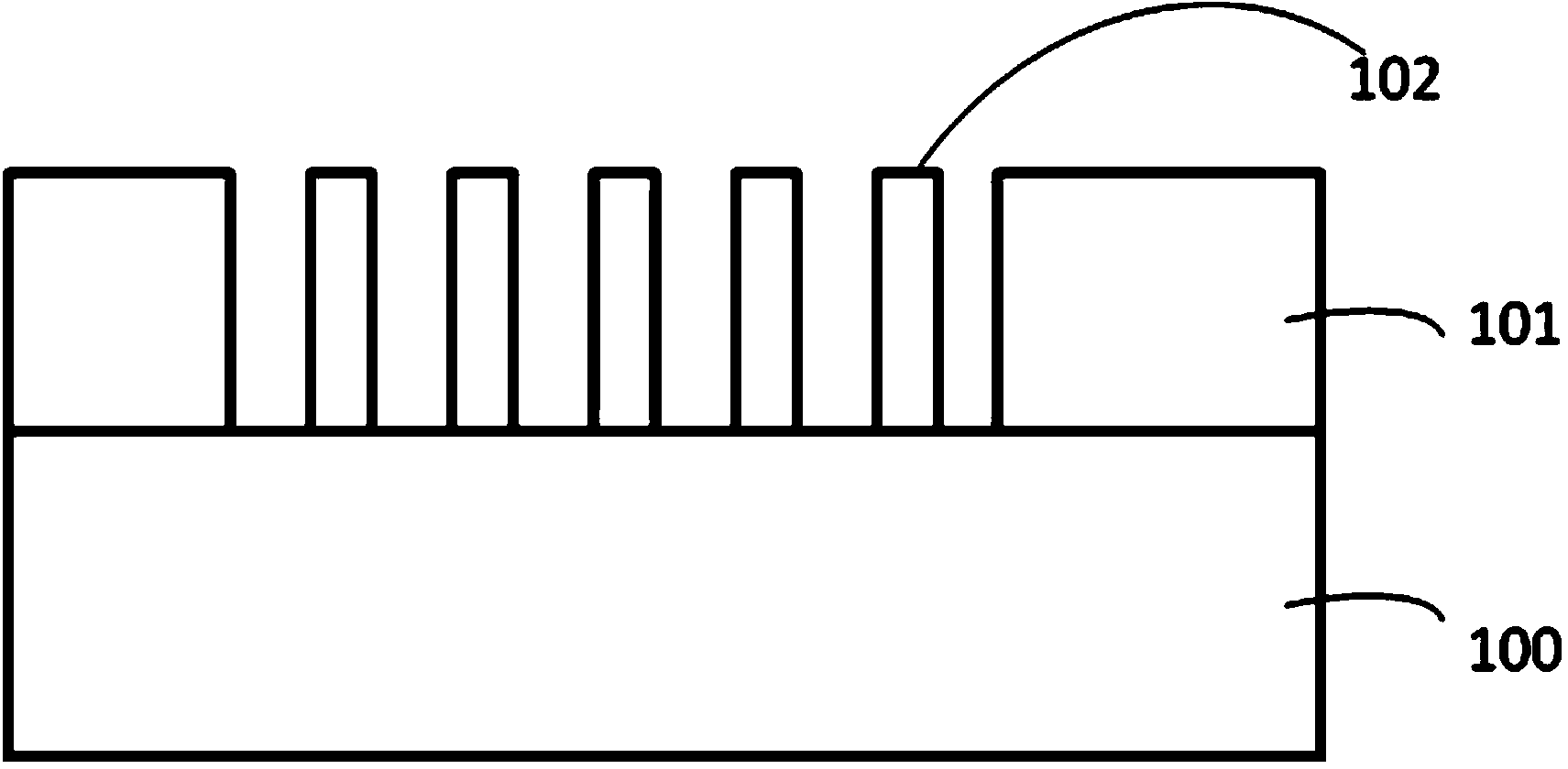
In the subsequent dry etching process, after the etching is completed, due to the small line width, under the high stress of the hard mask (HM) on the dielectric material, such as the TiN hard mask, it is very easy to The phenomenon that the dielectric film falls (collapses)

Method used


Image

  • Manufacturing method for thin film with ultralow dielectric constant
  • Manufacturing method for thin film with ultralow dielectric constant
  • Manufacturing method for thin film with ultralow dielectric constant

Examples


Embodiment Construction

[0024] The specific embodiment of the present invention will be further described in detail below in conjunction with the accompanying drawings.

[0025] It should be noted that, in the following specific embodiments, when describing the embodiments of the present invention in detail, in order to clearly show the structure of the present invention for the convenience of description, the structures in the drawings are not drawn according to the general scale, and are drawn Partial magnification, deformation and simplification are included, therefore, it should be avoided to be interpreted as a limitation of the present invention.

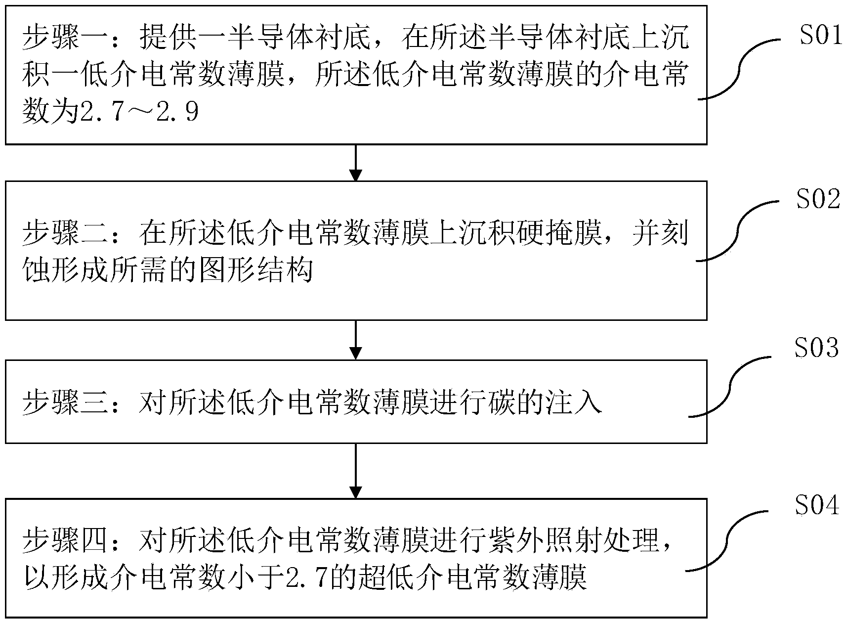
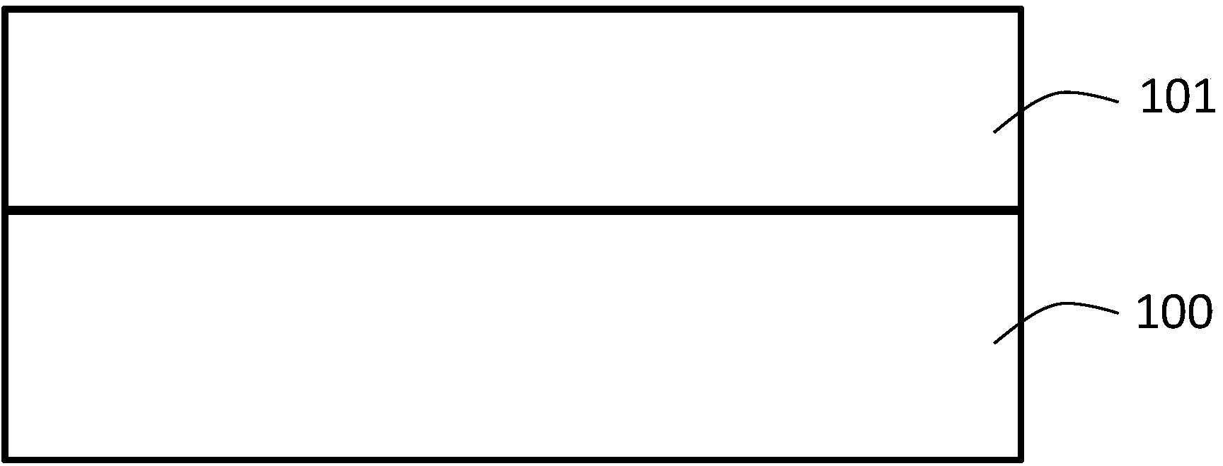
[0026] In this example, see figure 1 , figure 1 It is a flow chart of a manufacturing method of an ultra-low dielectric constant film of the present invention; at the same time, please refer to Figure 2 to Figure 5 , Figure 2 to Figure 5 is the application figure 1 Schematic diagram of the structure of an embodiment of manufacturing an ultra-lo...


PUM


Abstract

The invention discloses a manufacturing method for a thin film with an ultralow dielectric constant. A thin film with a low dielectric constant is etched, wherein the thin film is formed by deposition. A required pattern structure is formed (the porosity of a dielectric film is low at the moment, and the dielectric film has enough mechanical strength to support the high stress introduced by a hard mask), carbon injection and ultraviolet radiation are carried out to recover the aperture and the porosity of the dielectric film, the thin film with the ultralow dielectric constant is further formed, the phenomenon that the dielectric film collapses is avoided, and the effective dielectric constant (K value) of the dielectric film can be kept to be the smallest, and the method can be compatible with the existing industrial process.

Description

technical field [0001] The invention relates to the field of semiconductor integrated circuits, and more specifically, to a method for manufacturing an ultra-low dielectric constant film. Background technique [0002] In the semiconductor integrated circuit industry, high-performance integrated circuit chips require the lowest possible connection capacitance resistance signal delay and signal crosstalk. For this reason, low-resistivity copper metal lines and inter-layer and inter-line fillings are required. Low dielectric constant (Low-k) materials are used to reduce parasitic capacitance, thereby achieving the purpose of improving the device. The dielectric constant k value of the low dielectric constant material is generally 2.7 to 2.9. In the past ten years, research on ultra-low dielectric constant (ULK) materials has been increasing in the semiconductor industry, and the dielectric constant k value of ultra-low dielectric constant materials is required to be less than ...

Claims


Application Information

Patent Timeline
Patent Type & Authority Applications(China)
IPC IPC(8): H01L21/768
CPCH01L21/76825
Inventor 曾绍海李铭
Owner SHANGHAI INTEGRATED CIRCUIT RES & DEV CENT
Learn More