
A novel substrate integrated ridge waveguide structure

A technology of substrate integration and ridge waveguide, applied in the field of microwave guide, can solve problems such as incompatibility, and achieve the effect of improving the working bandwidth, increasing the ridge capacitance value, and expanding the scope of application

Inactive Publication Date: 2019-01-08
UNIV OF SHANGHAI FOR SCI & TECH
View PDF1 Cites 3 Cited by
  • Summary
  • Abstract
  • Description
  • Claims
  • Application Information

AI Technical Summary

Problems solved by technology

On the other hand, the single-mode operating bandwidth of SIW is limited to one octave, which is not suitable for wideband microwave systems

Method used


Image

  • A novel substrate integrated ridge waveguide structure
  • A novel substrate integrated ridge waveguide structure
  • A novel substrate integrated ridge waveguide structure

Examples


Embodiment Construction

[0019] In order to make the technical means, creative features, goals and effects of the present invention easy to understand, the following embodiments illustrate the novel substrate-integrated ridge waveguide structure of the present invention in detail with reference to the accompanying drawings.

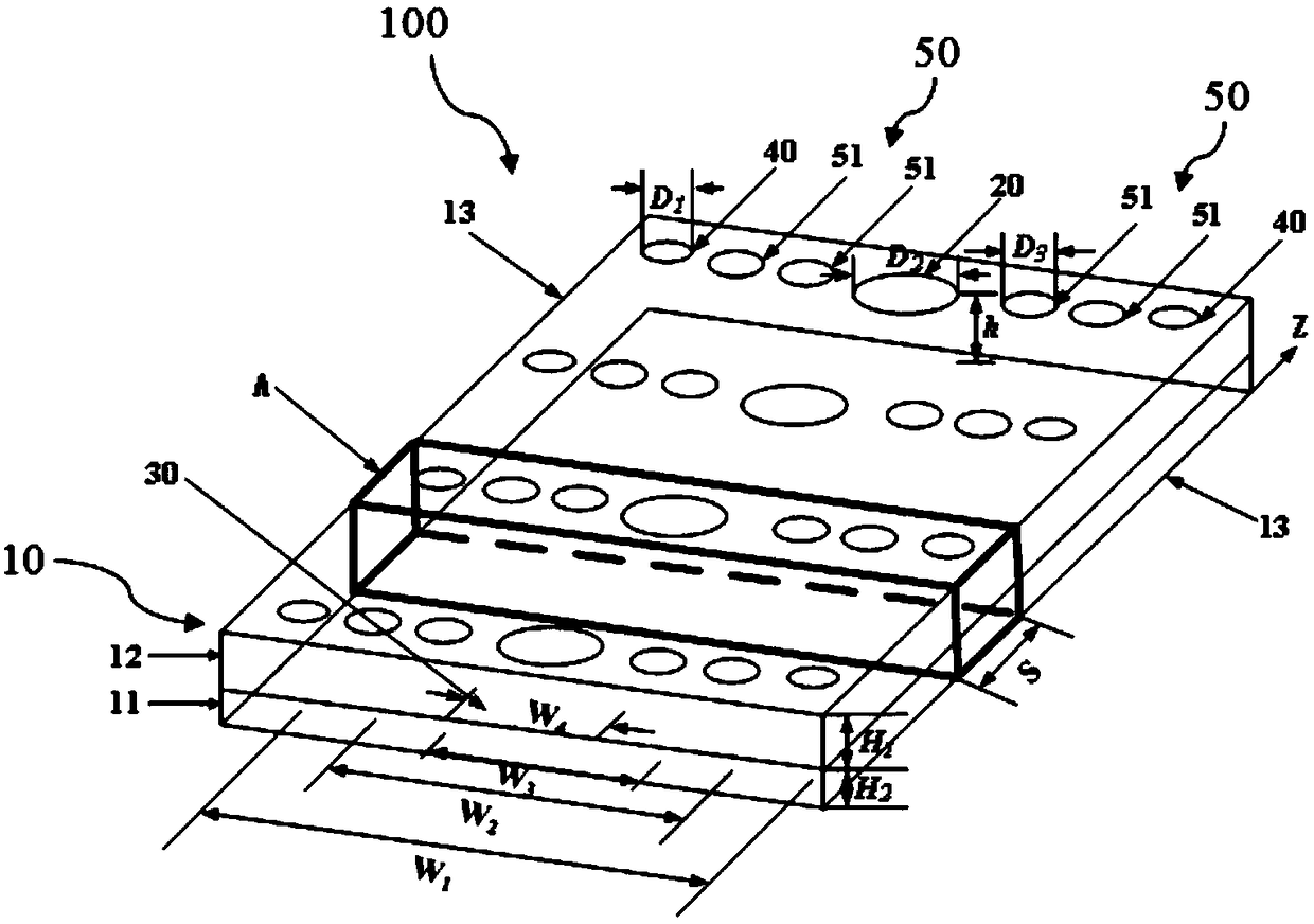
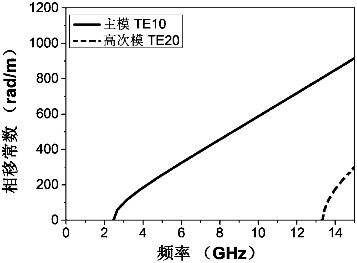
[0020] The main mode of the substrate integrated ridge waveguide structure 100 in this embodiment transmits the TE10 mode, and the high-order mode transmits the TE20 mode, and the working bandwidth of the main mode is the cut-off frequency of the high-order mode TE20 mode and the cut-off frequency of the main mode TE10 mode difference.

[0021] figure 1 is a structural schematic diagram of a novel substrate-integrated ridge waveguide structure in an embodiment of the present invention.

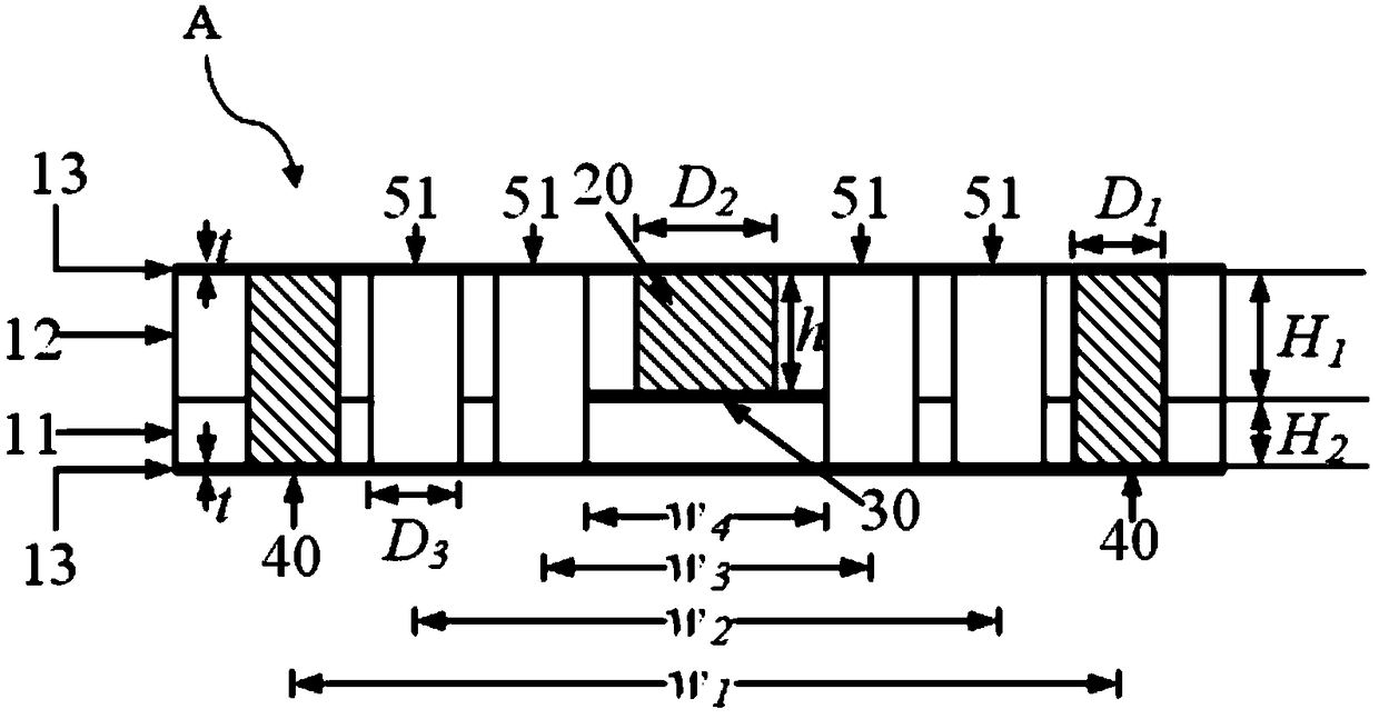
[0022] Such as figure 1 As shown, the novel substrate-integrated ridge waveguide structure 100 includes a dielectric substrate unit 10 , suspended metal pillars 20 , metal strips 30 , a pair of...


PUM


Abstract

The invention provides a novel substrate integrated ridge waveguide structure, comprising: a dielectric substrate unit, comprising a lower dielectric substrate and an upper dielectric substrate arranged on the lower dielectric substrate, wherein the dielectric constant of the upper dielectric substrate is different from that of the lower dielectric substrate. A suspended metal column embedded in the upper dielectric substrate along a direction perpendicular to the dielectric substrate unit and periodically arranged on a centerline in the longitudinal direction of the upper dielectric substrate; And a metal strip arranged at the bottom of the suspended metal column. The novel substrate integrated ridge waveguide is composed of two dielectric substrates with different dielectric constants. The gap between the lower surface of the suspended metal column embedded in the structure and the lower surface of the dielectric substrate unit forms the ridge capacitance, which reduces the cutoff frequency of the main mode. In addition, the area between the electrode plates is increased by the metal strips arranged at the bottom of the suspended metal column, so that the ridge capacitance valueis increased, the cutoff frequency of the main mode is further reduced, and the working bandwidth of the obtained main mode is greatly improved.

Description

technical field [0001] The invention relates to the field of microwave guide technology, in particular to a novel substrate integrated ridge waveguide structure. Background technique [0002] With the development of microwave and millimeter wave technology in the field of wireless communication and radar systems, the use of low-cost, high-reliability integrated circuits has become increasingly widespread. Metal waveguides have the advantages of high quality factor (Q) and low loss. However, metal waveguides similar to rectangular waveguides are bulky and costly, which limits their development in the direction of miniaturization and integration. [0003] Substrate integrated waveguide (Substrate integrated waveguide, SIW) is a high-performance, low-loss miniaturized transmission line proposed in recent years. Periodic metal vias are used to replace the metal sidewall of the traditional rectangular waveguide. Its electromagnetic wave propagation characteristics are similar to ...

Claims


Application Information

Patent Timeline
IPC IPC(8): H01P3/123
CPCH01P3/123
Inventor 王宁许涛马艳颍高聪马志豪孟丛张坤陈加骏唐小玉贾宏志
Owner UNIV OF SHANGHAI FOR SCI & TECH
Learn More