Pad conditioning force modeling to achieve constant removal rate

a technology of force modeling and conditioning disk, which is applied in the direction of abrasive surface conditioning devices, lapping machines, manufacturing tools, etc., can solve the problems of drifting polishing pad effectiveness, affecting the uniformity of the results from substrate to substrate, and the effect of the conditioning disk is reduced

Inactive Publication Date: 2013-05-16
APPLIED MATERIALS INC
View PDF26 Cites 23 Cited by
  • Summary
  • Abstract
  • Description
  • Claims
  • Application Information

AI Technical Summary

Benefits of technology

[0046]Thus, a methodology has been provided to maintain constant removal rates over the life of a conditioning disk. Embodiments of the invention advantageously compensate for loss of conditioning effectiveness to maintain a desired process performance. The methodology may be utilized in-situ as a running process, or as a feedback routine to substantially eliminate process drift. Additionally, embodiments of the invention advantageously extend the useful lifetime of polishing pads by determining a reduced down force still sufficient to achieve a specified sweep torque target. Consequently, embodiments of the invention advantageously reduce excessive polishing pad wear due to over-conditioning, for example, when the conditioning disk is new and freshly abrasive. According to certain embodiments, the pad lifetime may be improved by 20% to 60% over conventional approaches. Likewise, it is understood that embodiments of the invention advantageously increase the useful lifetime of conditioning disks.
[0047]While the foregoing is directed to embodiments of the present invention, other and further embodiments of the invention may be devised without departing from the basic scope thereof, and the scope thereof is determined by the claims that follow. For example, while the foregoing is directed to embodiments of the present invention focused on a sweep torque of a conditioning disk, it is contemplated that torques measured throughout a CMP system, such as at other motors or actuators, may be used to determine a model force profile for controlling the polisher.

Problems solved by technology

It is generally known that the effectiveness of the conditioning disk declines over time due to disk and pad wear.
As a result, the effectiveness of the polishing pad drifts over time, producing non-uniform results from substrate to substrate.

Method used


Image

  • Pad conditioning force modeling to achieve constant removal rate
  • Pad conditioning force modeling to achieve constant removal rate
  • Pad conditioning force modeling to achieve constant removal rate

Examples


Embodiment Construction

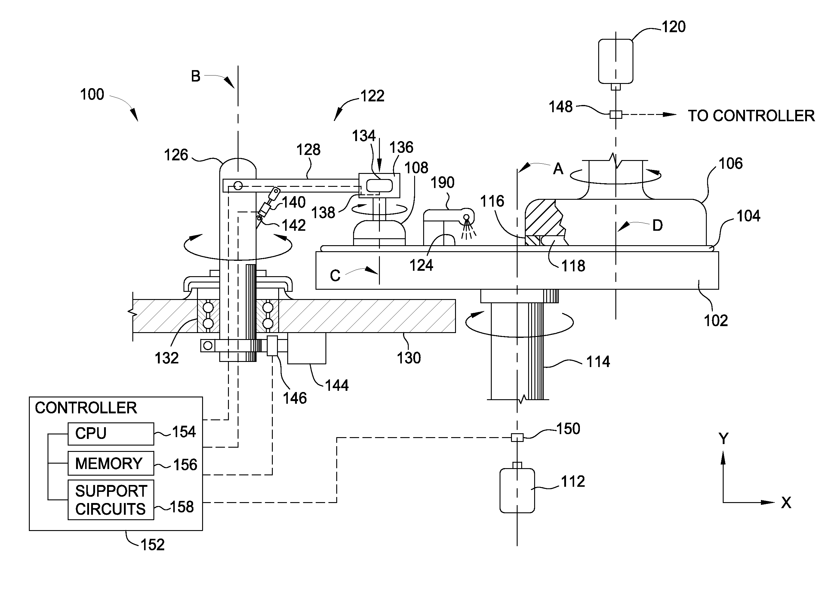
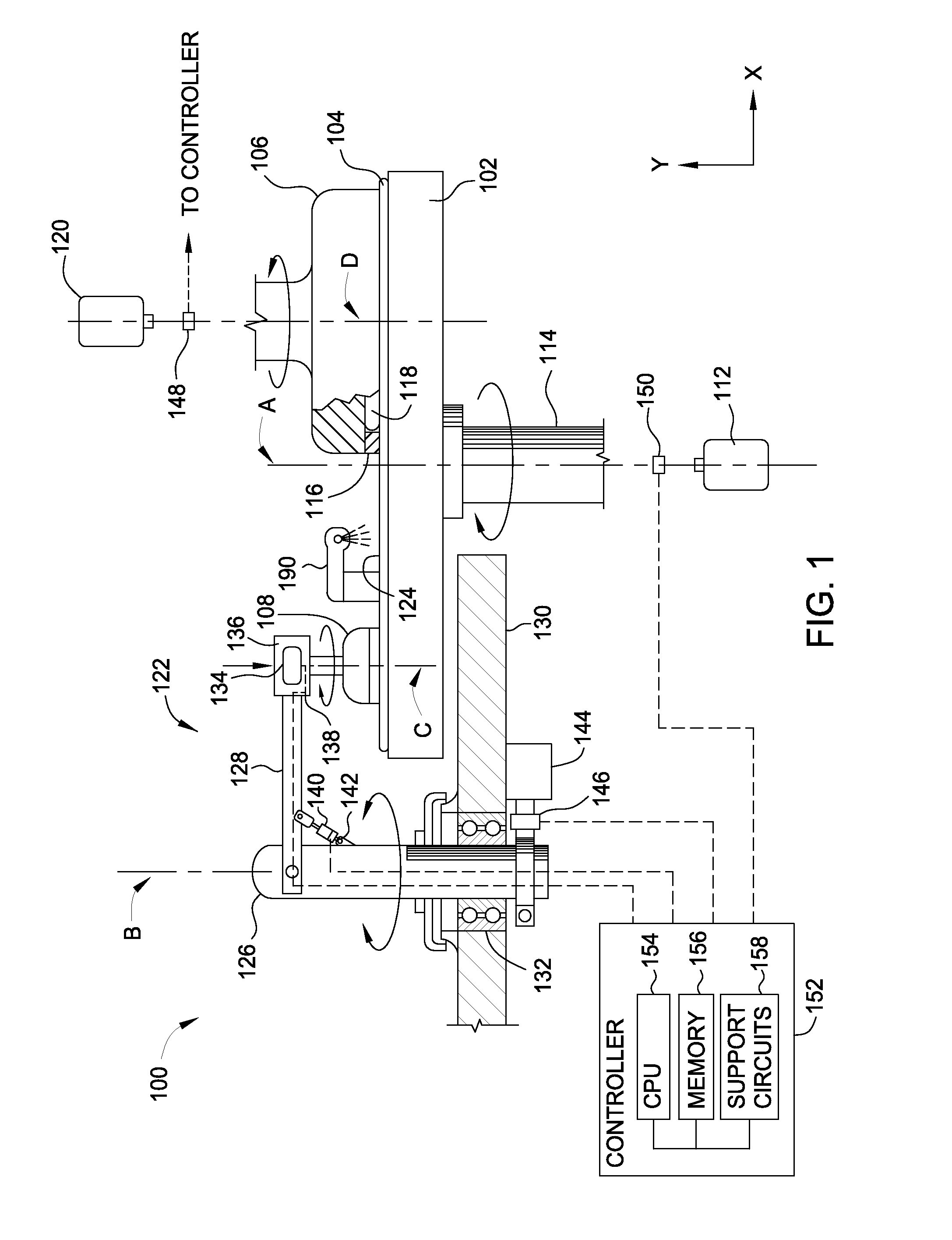
[0015]Embodiments of the invention are directed towards the performance of a CMP polishing pad. Embodiments of the disclosure provide a method and apparatus for controlling a CMP polisher based on a relationship between conditioning arm sweep torque and friction between the polishing pad and conditioning disk. Embodiments include a method for adjusting a down-force (down force) applied by a conditioning disk to a polishing pad based on a difference between a measured force and a modeled force profile to improve processing results. It is contemplated that aspects of the present disclosure that enable use of conditioner sweep torque to monitor polisher performance may be applied in real time and / or when the polishing pad is being conditioned while a substrate is being polished (i.e., in-situ conditioning), when the polishing pad is conditioned in-between substrate polishing (i.e., ex-situ conditioning), or any combination thereof.

[0016]FIG. 1 is a sectional view of one embodiment of a...


PUM


Abstract

A method and apparatus for conditioning a polishing pad in a CMP system is provided. In one embodiment, a method for conditioning a polishing pad includes applying a down force to the conditioning disk that urges the conditioning disk against the polishing pad, measuring a torque required to sweep the conditioning disk across the polishing pad, determining a change in down force by comparing the measured torque to a model force profile (MFP), and adjusting the down force that the conditioning disk applies against the polishing pad in response to the determined change.

Description

BACKGROUND[0001]1. Field of the Invention[0002]Embodiments of the present invention generally relate a method for conditioning a polishing surface in an electrochemical mechanical processing system.[0003]2. Description of the Related Art[0004]During the manufacture of semiconductor devices, layers and structures are deposited and formed on a semiconductor substrate by various processes. Chemical mechanical polishing (CMP) is a widely used process by which a polishing pad in combination with a polishing solution removes excess material in a manner that planarizes the substrate or maintains flatness for receipt of a subsequent layer. Over time, the effectiveness of the polishing pad diminishes as pressure, friction, and heat combine with particulate matter from processing slurries, materials removed from the substrate (or from the pad itself), and the like, to form a hard, relatively smooth surface on the pad. This effect is typically called “glazing.” In order to improve the effectiv...

Claims


Application Information

Patent Timeline
Patent Type & Authority Applications(United States)
IPC IPC(8): B24B53/017
CPCB24B53/017B24B37/042B24B37/00B24B53/00H01L21/304
Inventor MENK, GREGORY E.TSAI, STAN D.CHO, SANG J.DHANDAPANI, SLVAKUMARCOCCA, CHRISTOPHER D.FUNG, JASON G.CHANG, SHOU-SUNGGARRETSON, CHARLES C.
Owner APPLIED MATERIALS INC
Why Eureka
Try Eureka