Self-calibration method for angle detector, angle detector, circumferential scale calibration device, and angle detector calibration device

a self-calibration method and calibration method technology, applied in measurement devices, instruments, surveying and navigation, etc., can solve the problems of sampling theorem imposing limitations, the integer interval of equal division of angle interval between the two scale reader heads is lost from calibration, and the scale error cannot be reliably computed

Active Publication Date: 2013-05-16
HARMONIC DRIVE SYST IND CO LTD +1
View PDF2 Cites 4 Cited by
  • Summary
  • Abstract
  • Description
  • Claims
  • Application Information

AI Technical Summary

Benefits of technology

[0019]The sequential two-point method has a limitation in that the error component in the integer interval of equal division of the angle interval between the two scale reader heads is lost from the calibration result. In the invention of the present application, the first and second scale reader heads are disposed at an angle interval α such that a pluralit

Problems solved by technology

The sequential two-point method has not been used conventionally as a method for calibrating rotary encoders.
The main reason for this is that the error component in the integer interval of equal division of the angle interval between the two scale reader heads is lost from the calibration result.
In this case, the sampling theorem imposes a limitation in that only frequency components up to the k/2th frequen

Method used


Image

  • Self-calibration method for angle detector, angle detector, circumferential scale calibration device, and angle detector calibration device
  • Self-calibration method for angle detector, angle detector, circumferential scale calibration device, and angle detector calibration device
  • Self-calibration method for angle detector, angle detector, circumferential scale calibration device, and angle detector calibration device

Examples


Embodiment Construction

[0027]Embodiments of the present invention are described below with reference to the accompanying drawings.

[0028](Configuration of Self-Calibration Device)

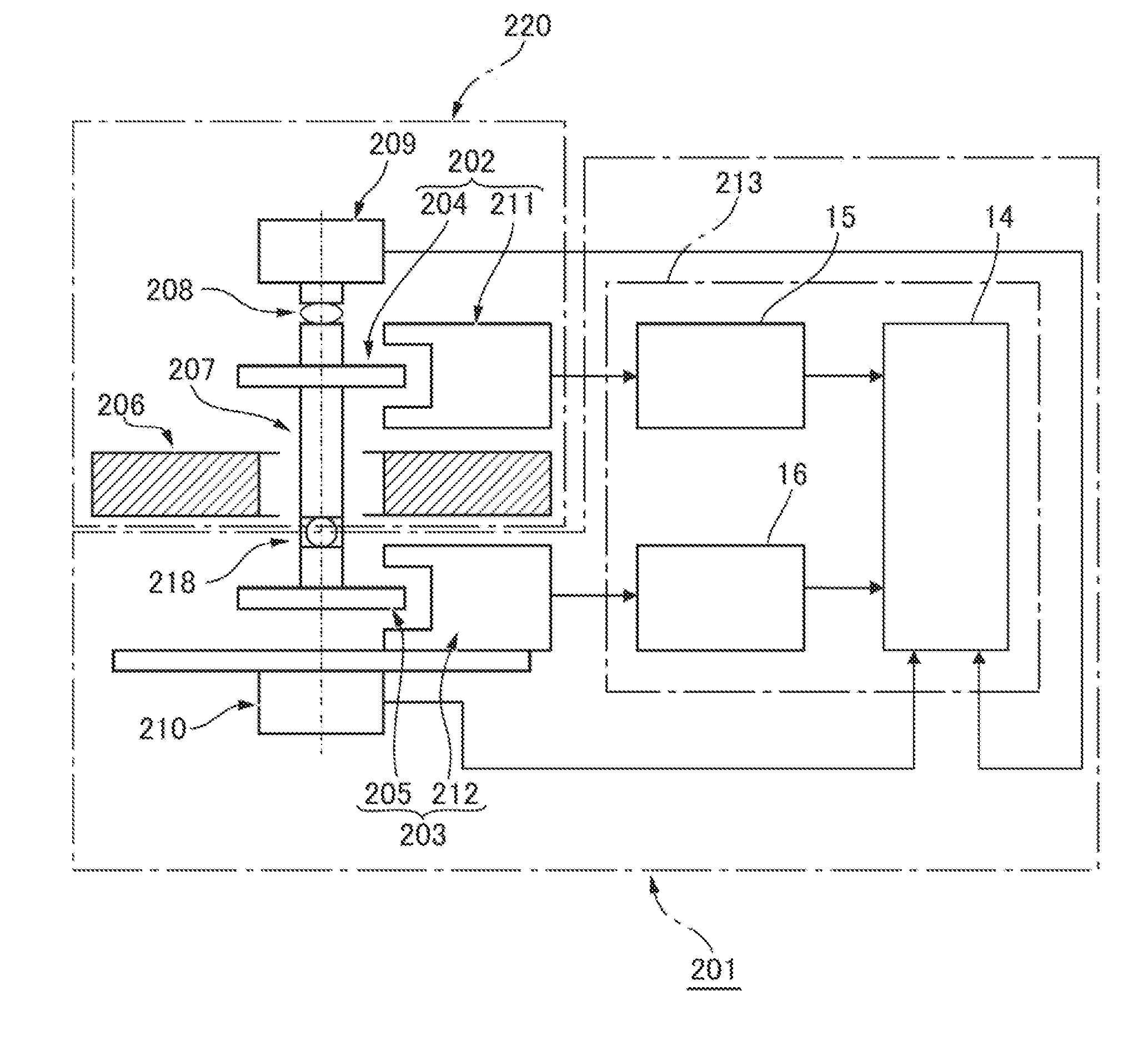
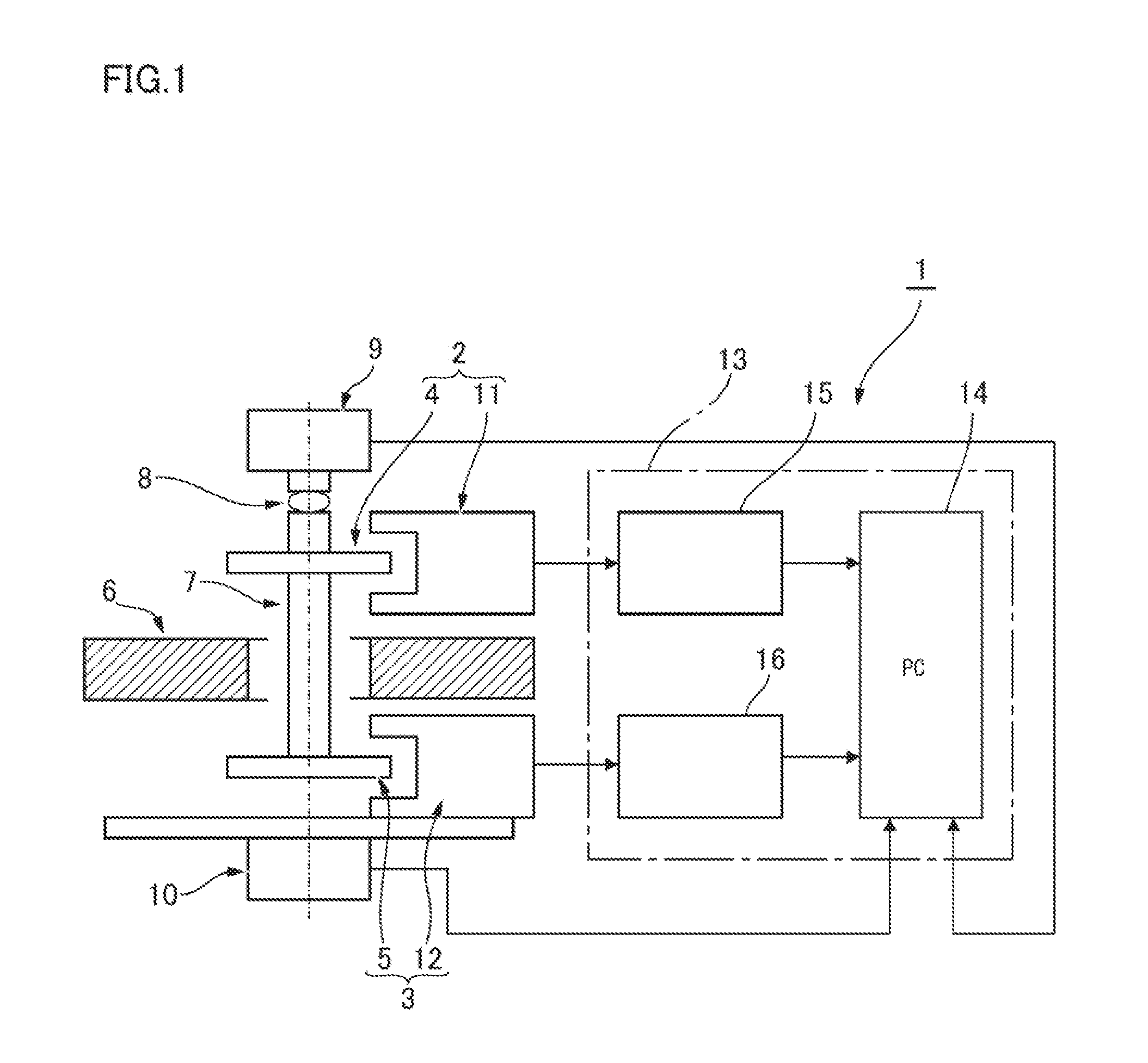
[0029]First, FIG. 1 is a view showing the general configuration of an example of a self-calibration device for a rotary encoder according to an embodiment of the present invention. The self-calibration device 1 for a rotary encoder (hereinafter, “self-calibration device 1”) is provided with two rotary encoders. One rotary encoder is a fixed-side rotary encoder 2, and the other rotary encoder is a phase adjustment-side rotary encoder 3. The fixed-side rotary encoder 2 is provided with a divided circle 4 and a scale reader head 11. The phase adjustment-side rotary encoder 3 is provided with a divided circle 5 and a scale reader head 12.

[0030]The divided circle 4 of the rotary encoder 2 and the divided circle 5 of the rotary encoder 3 are each coaxially fixed to a shaft 7 supported by a bearing 6. A motor 9 for continuous rotation of...


PUM


Abstract

In a self-calibration method of an angle detector, an angle interval between first and second scale reader heads are set, so that a single rotation is not equally divided into an integer number of potions by a value of the angle interval and that a plurality of rotations N are equally divided into M equal portions by the value of the angle interval. Readings by the scale reader heads during N rotations of the divided circle are obtained at a pre-set data sampling interval. From differences in readings by these scale reader heads, data of the sequential two-point method relating to an angle scale error of the divided circle are obtained at the data sampling interval. The scale error of the divided circle at the data sampling interval is calculated by synthesizing the data using the fact that an average of the data for the rotations N reaches approximately zero.

Description

TECHNICAL FIELD[0001]The present invention relates to a self-calibration method for an angle detector that uses a sequential two-point method, to an angle detector that uses the self-calibration method, to a circumferential scale calibration device, and to a calibration device.BACKGROUND ART[0002]Known methods for calibrating a so-called rotary encoder, which is an angle detector having a scale reader head on the periphery of a rotating divided circle, include methods that use comparison calibration, the equally divided average method, and other methods. Calibration using the equally divided average method is described in Patent Documents 1 and 2.[0003][Patent Document 1] Japanese Laid-open Patent Publication No. 2006-098392[0004][Patent Document 2] Japanese Laid-open Patent Publication No. 2011-099804[0005]A sequential two-point method may be used to calibrate a rotary encoder. When the sequential two-point method is used, calibration can be performed using two scale reader heads. ...

Claims


Application Information

Patent Timeline
IPC IPC(8): G06F19/00G01B21/22
CPCG01D5/24452G01D18/001
Inventor YAMAZAKI, HIROSHIHANAOKA, HIROKIKIYONO, SATOSHI
Owner HARMONIC DRIVE SYST IND CO LTD
Why Eureka
Try Eureka