Chemical looping system

a looping system and looping technology, applied in the direction of fluidised bed combustion apparatus, combustion types, lighting and heating apparatus, etc., can solve the problems of inability to achieve the strength and redox activity of the target material, and achieve the effect of easy separation and enhanced h2 generation

Inactive Publication Date: 2013-05-23
SIEMENS AG
View PDF5 Cites 10 Cited by
  • Summary
  • Abstract
  • Description
  • Claims
  • Application Information

AI Technical Summary

Benefits of technology

[0017]According to yet another embodiment, wherein the reformer gas comprises H2, CO, C2O and H2O. The H2 of the reformer gas can be used as a fuel. Additional H2 can be obtained by reacting CO and H2O in a shift reactor. The CO2 can easily be separated from H2, and the separated CO2 is sequestration ready as the same is separate fro

Problems solved by technology

In both cases, the target material performance with r

Method used


Image

  • Chemical looping system

Examples


Embodiment Construction

[0023]Various embodiments are described with reference to the drawings, wherein like reference numerals are used to refer to like elements throughout. In the following description, for purpose of explanation, numerous specific details are set forth in order to provide a thorough understanding of one or more embodiments. It may be evident that such embodiments may be practiced without these specific details.

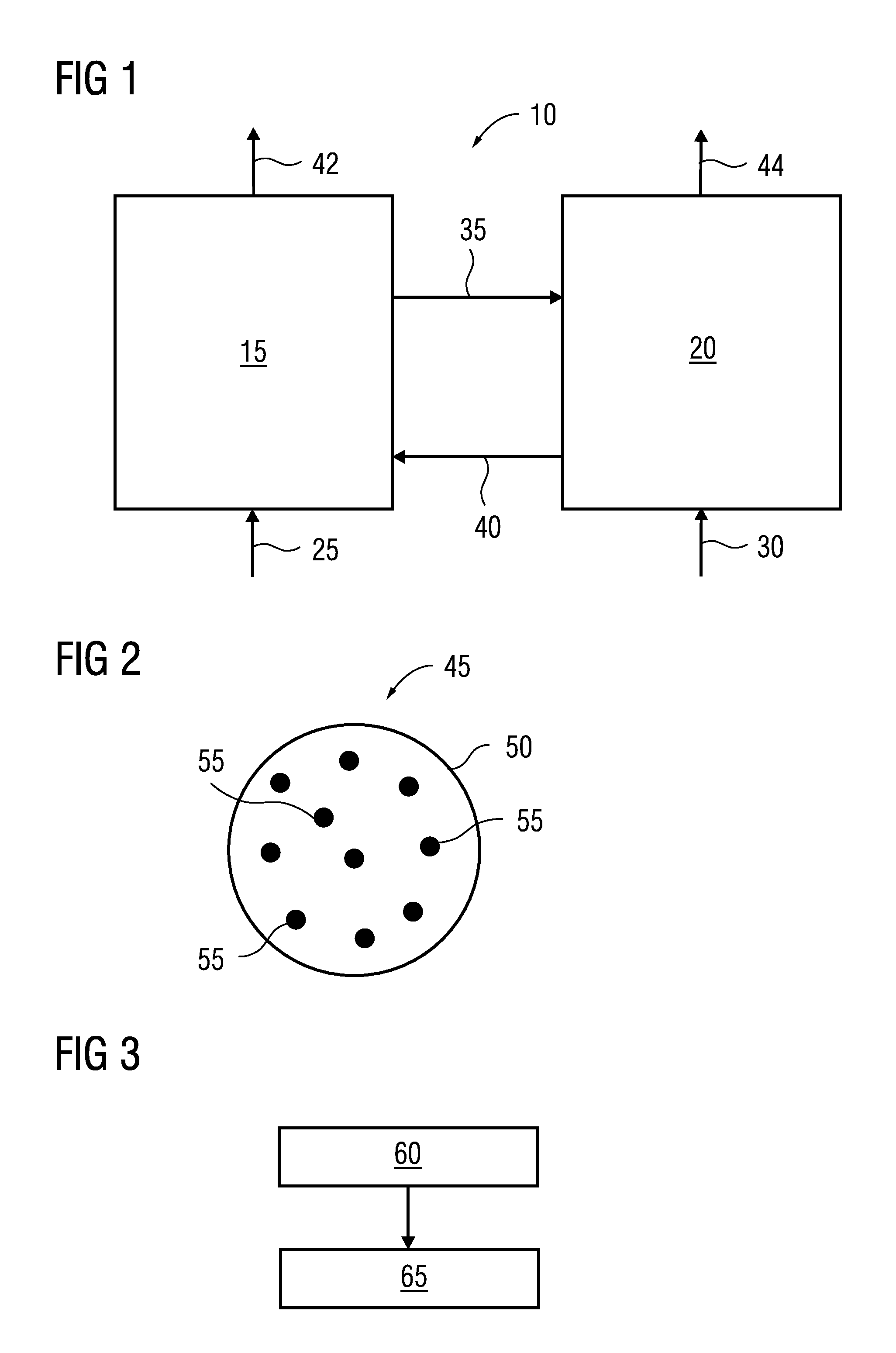
[0024]FIG. 1 illustrates a schematic block diagram of a chemical looping system according to an embodiment herein. As illustrated in the example of FIG. 1, the chemical lopping system 10 comprises an air reactor 15 and a fuel reactor 20. Typically, the air reactor 15 and the fuel reactor 20 are fluidized bed reactors. In the present example of FIG. 1, air is supplied as oxidant is into the air reactor 15, as designated by the arrow 25. A fuel is supplied into the fuel reactor 20, as designated by the arrow 30. The air reactor 15 and the fuel reactor are isolated and thus, there is...


PUM


Abstract

A chemical looping system and a method of transferring oxygen therein are provided. The system has an air reactor adapted to receive air for oxidizing an oxygen carrier, a fuel reactor adapted to receive a fuel and the oxidized oxygen carrier for at least partially oxidizing the fuel by reducing the oxygen carrier to produce a gas. The oxygen carrier has oxide-dispersion-strengthened alloy particles.

Description

CROSS REFERENCE TO RELATED APPLICATIONS[0001]This application is the US National Stage of International Application No. PCT / EP2010 / 061200 filed Aug. 2, 2010 and claims the benefit thereof. The application is incorporated by reference herein in its entirety.FIELD OF THE INVENTION[0002]The present invention relates to a chemical looping system and a method of transferring oxygen between therein.BACKGROUND OF THE INVENTION[0003]Chemical looping is a combustion technology with inherent separation of greenhouse gas CO2. The technique involves the use of a metal oxide as an oxygen carrier for transferring oxygen from the air reactor to the fuel reactor. Thus, direct contact between fuel and air is avoided. The output product of oxidation of fuel, i.e., carbon dioxide, is kept separate from the rest of the flue gases, such as nitrogen and any un-reacted oxygen. Two reactors, i.e., the air reactor and the fuel reactor having interconnected fluidized beds are used for this process. The metal...

Claims


Application Information

Patent Timeline
IPC IPC(8): C10L3/10
CPCF23C10/005F23C99/00Y02E20/346C10L3/10F23C2900/99008Y02E20/34
Inventor GREINER, HORSTZAMPIERI, ALESSANDRO
Owner SIEMENS AG
Why Eureka
Try Eureka