Thermal energy storage and recovery system comprising a storage arrangement and a charging/discharging arrangement being connected via a heat exchanger

a technology of thermal energy storage and recovery system, which is applied in the direction of steam engine plants, machines/engines, mechanical equipment, etc., can solve the problems of large amount of gas not being effectively used, large enclosure needs to be large, etc., and achieves low cost, high heat storage capability, and relatively low heat conductance between rocks

Inactive Publication Date: 2013-05-23
SIEMENS AG
View PDF15 Cites 47 Cited by
  • Summary
  • Abstract
  • Description
  • Claims
  • Application Information

AI Technical Summary

Benefits of technology

[0038]According to a further embodiment, the heat storage material comprises rock material and/or sand material. This may provide the advantage that a low cost and widely available material can be used for building up the thermal energy storage device. Thereby, local labor and locally available heat storage material can be used such that there is no need to transport a suitable heat storage material over a long distance. This may be in particular advantageous if a thermal energy storage device with a high heat storage capability is built up.
[0039]It is mentioned that in many applications rocks may be preferred since rocks are inexpensive and ...

Problems solved by technology

Further, since the storage method has the capacity to store very large quantities of energy the installation for storing and returning electrical energy would use an enclosure having very...

Method used


Image

  • Thermal energy storage and recovery system comprising a storage arrangement and a charging/discharging arrangement being connected via a heat exchanger
  • Thermal energy storage and recovery system comprising a storage arrangement and a charging/discharging arrangement being connected via a heat exchanger
  • Thermal energy storage and recovery system comprising a storage arrangement and a charging/discharging arrangement being connected via a heat exchanger

Examples


Embodiment Construction

[0054]The illustration in the drawing is schematically. It is noted that in different figures, similar or identical elements are provided with the same reference signs or with reference signs, which are different from the corresponding reference signs only within the first digit.

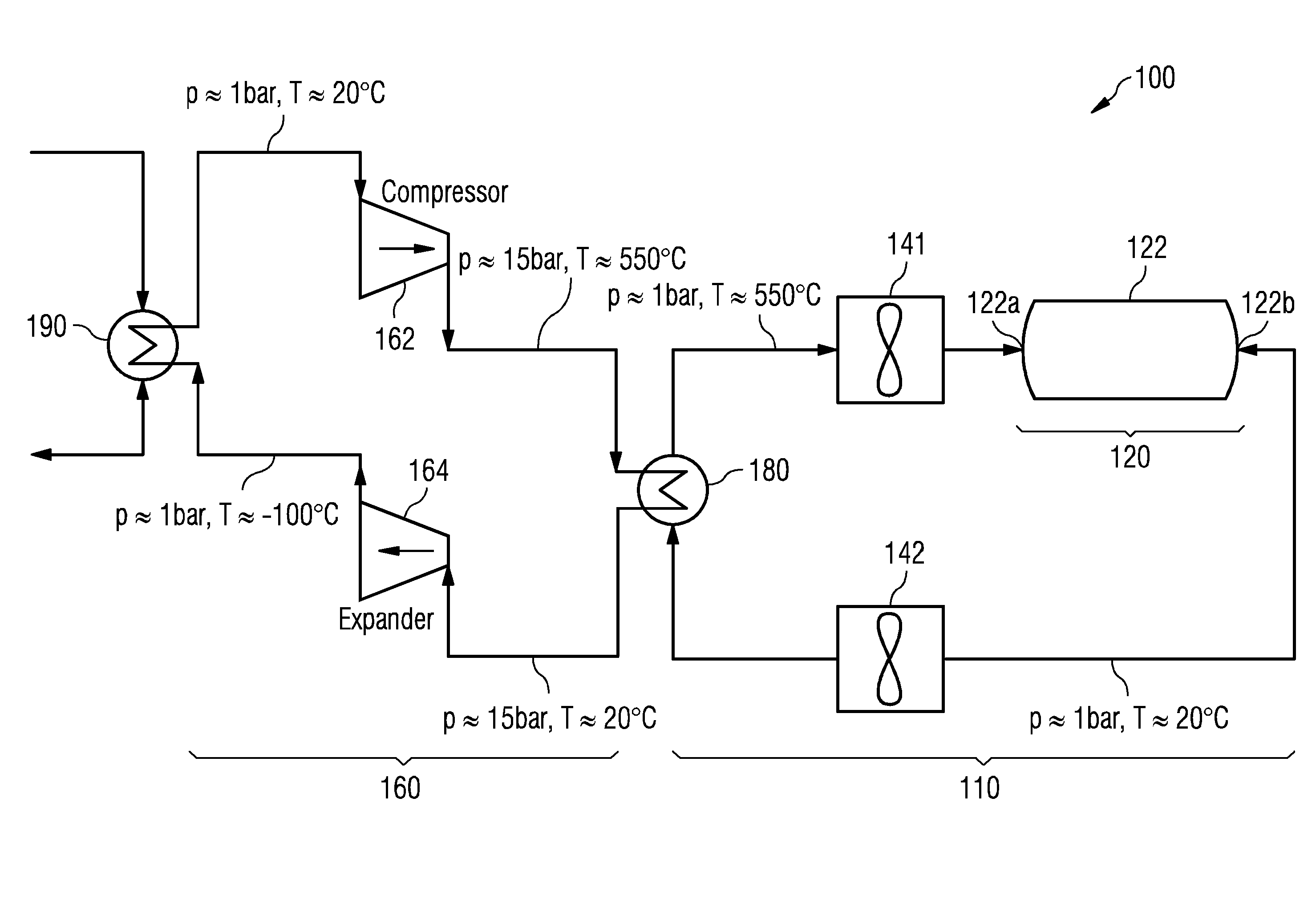
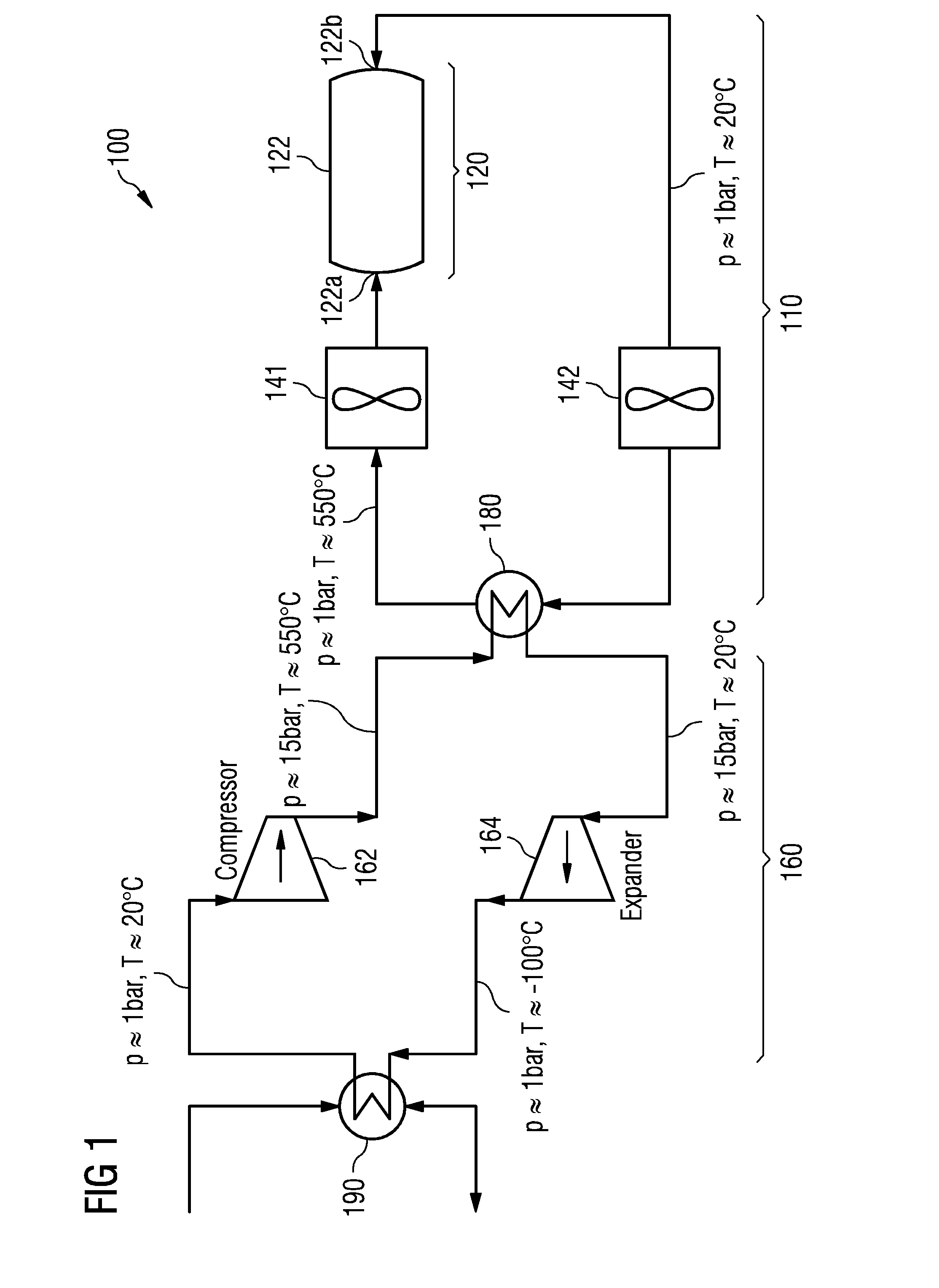
[0055]FIG. 1 shows a thermal energy storage and recovery system 100 comprising a thermodynamic storage arrangement 110 and a thermodynamic charging / discharging arrangement 160. The thermal energy storage and recovery system 100 further comprises an air-to-air heat exchanger 180 which thermodynamically couples the storage arrangement 110 with the charging / discharging arrangement 160.

[0056]According to the embodiment described here the storage arrangement 110 comprises a thermal energy storage device 120 having a container 122 being filled with a non depicted heat storage material and two fluid terminals, a first fluid terminal 122a and a second fluid terminal 122b. One fluid terminal is used for inserting a h...


PUM


Abstract

A thermal energy storage and recovery system including a storage arrangement having a thermal energy storage device for temporarily storing thermal energy, a charging/discharging arrangement having a fluid energy machine for exchanging mechanical work with a working fluid cycling through the charging/discharging arrangement, and a heat exchanger which is arranged between the storage arrangement and the charging/discharging arrangement and which thermodynamically couples a heat transfer fluid cycling through the storage arrangement with the working fluid is provided. The storage arrangement is configured in such a manner that the heat transfer fluid is under a first pressure and the charging/discharging arrangement is configured in such a manner that the working fluid is at least partially under a second pressure, wherein the second pressure is higher than the first pressure.

Description

CROSS REFERENCE TO RELATED APPLICATIONS[0001]This application claims priority of European Patent Office application No. 11189939.9 EP filed Nov. 21, 2011. All of the applications are incorporated by reference herein in their entirety.FIELD OF INVENTION[0002]The field of invention relates to temporarily storing and recovering thermal energy. A thermal energy storage and recovery system comprising a storage arrangement having a thermal energy storage device for temporarily storing thermal energy and a charging / discharging arrangement for (a) charging, in a first operational mode, the thermal energy storage device and for (b) discharging, in a second operational mode, the thermal energy storage device is provided.ART BACKGROUND[0003]The production of electric power from various types of alternative energy sources such as for instance wind turbines, solar power plants and wave energy plants is not continuous. The production may be dependent on environmental parameters such as for instan...

Claims


Application Information

Patent Timeline
IPC IPC(8): F01K13/00
CPCF01K13/006Y02E20/14F01K3/00
Inventor BARMEIER, TILLCOURTET, GILDAS JEANCRONIN, AIDANLAURBERG, HANSPETERSEN, JESPER ELLIOTSTIESDAL, HENRIK
Owner SIEMENS AG
Why Eureka
Try Eureka