Piezoelectric foam structures and hydrophone utilizing same

a technology of piezoelectric foam and hydrophone, which is applied in the direction of piezoelectric/electrostrictive device material selection, basic electric elements, device material selection, etc., can solve the problems that conventional studies or systems do not provide a comprehensive study of the electromechanical properties of piezoelectric foam structures for synthesis from elastically anisotropic materials

Inactive Publication Date: 2013-05-23
THE RES FOUND OF STATE UNIV OF NEW YORK
View PDF2 Cites 4 Cited by
  • Summary
  • Abstract
  • Description
  • Claims
  • Application Information

AI Technical Summary

Benefits of technology

[0014]However, a comprehensive study of the electromechanical properties of piezoelectric foam structures for synthesis from elastically anisotropic materials is not provided by conventional studies or systems. Accordingly, the present invention provides a numerical model based analysis of piezoelectric materials that is based on modeling of a combination of bending and axial deformation of the piezoelectric struts.
[0015]The present invention overcomes the above shortcoming of conventional methods and systems and provides a piezoelectric foam formed of elastically anisotropic materials. The piezoelectric foam includes a unit cell of an elastically anisotropic material having a relative density / volume fraction and specified deformation that are specified by subjecting the unit cell to controlled mechanical and electrical loading conditions. Resultant stress and electric displacements field components are measured by capturing a homogeneous coupled response of the unit cell, and by computing piezoelectric material constants using the captured homogeneous coupled response, to identify type F1, F2 and F3 piezoelectric foam structures.

Problems solved by technology

While much recent work has focused on understanding the properties of metallic foams, few efforts have also been made to understand and characterize the structural properties of ceramic foams as well.
However, a comprehensive study of the electromechanical properties of piezoelectric foam structures for synthesis from elastically anisotropic materials is not provided by conventional studies or systems.

Method used


Image

  • Piezoelectric foam structures and hydrophone utilizing same
  • Piezoelectric foam structures and hydrophone utilizing same
  • Piezoelectric foam structures and hydrophone utilizing same

Examples


Embodiment Construction

[0026]The following detailed description of embodiments of the invention will be made in reference to the accompanying drawings. In describing the invention, explanation of related functions or constructions known in the art are omitted for the sake of clarity in understanding the concept of the invention that would otherwise obscure the invention with unnecessary detail.

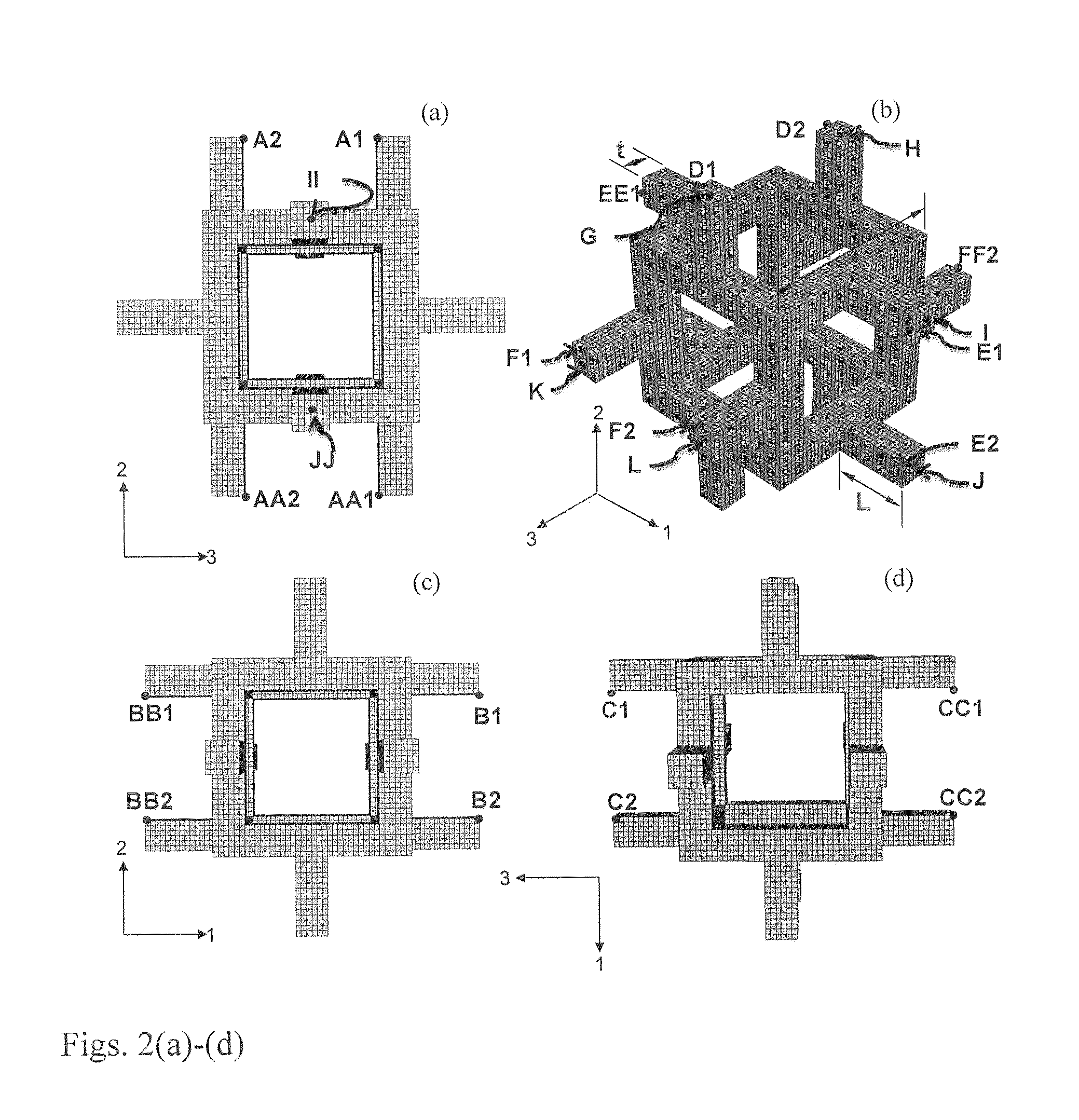
[0027]Set forth below are a classification of porous piezoelectric foam structures, a description of constitutive relationships describing coupled behavior of piezoelectric materials, details of the finite element based numerical models developed in the present invention to characterize the electromechanical properties of piezoelectric foam structures, and improvements in electromechanical properties of piezoelectric foams structures.

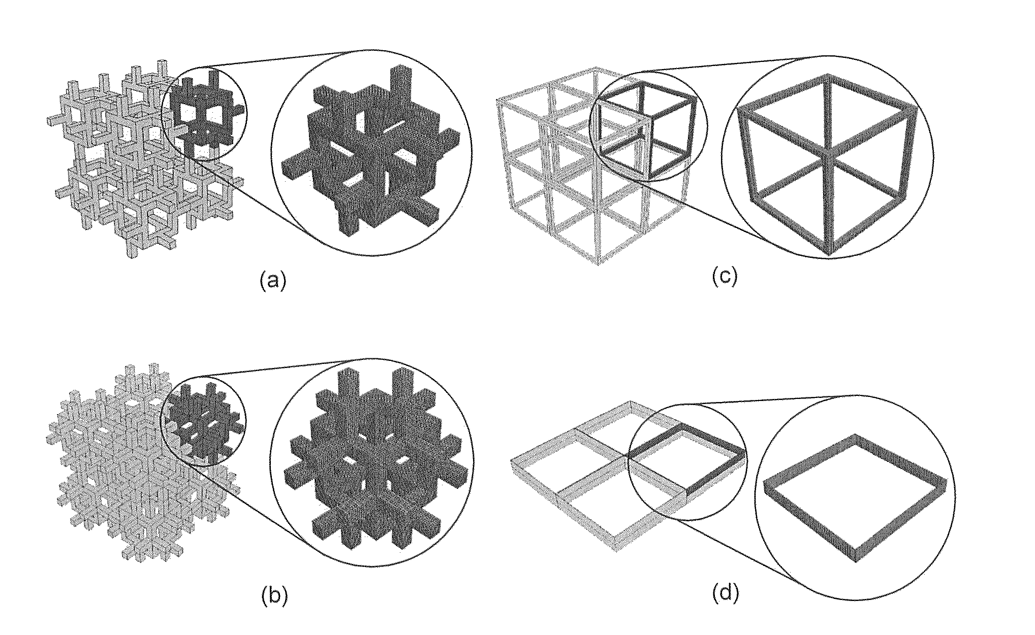
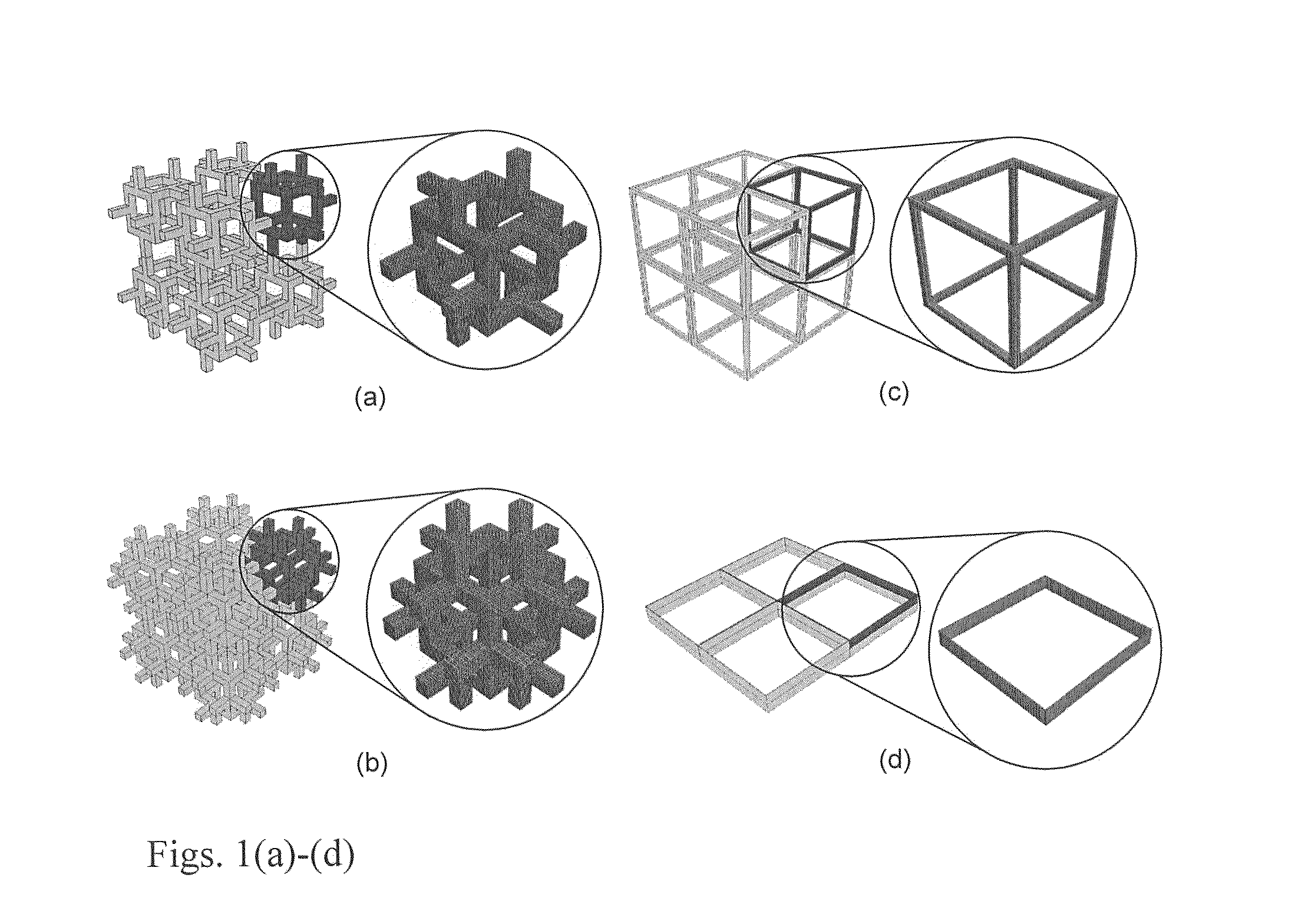
[0028]In general, porous piezoelectric materials are classified into three distinct types: (i) 3-0 type, where the porosity is enclosed in all three dimensions by a matrix phase; (ii) 3...


PUM

PropertyMeasurementUnit
elastically anisotropicaaaaaaaaaa
relative density/volume fractionaaaaaaaaaa
piezoelectricaaaaaaaaaa

Abstract

Disclosed is a piezoelectric foam formed of elastically anisotropic materials. The piezoelectric foam is defined with a unit cell having a relative density and volume fraction, and deformation specified by subjecting the unit cell to controlled mechanical and electrical loading conditions. Resultant stress and electric displacements field components are measured by capturing a homogeneous coupled response of the unit cell and by computing piezoelectric material constants using the captured homogeneous coupled response, to identify asymmetric and symmetric F1, F2 and F3 type piezoelectric foam structures.

Description

PRIORITY[0001]This application claims priority to U.S. Provisional Applications No. 61 / 561,085, 61 / 561,097 and 61 / 561,103, each filed Nov. 17, 2011, the contents of each of which are incorporated herein by reference.BACKGROUND OF THE INVENTION[0002]1. Field of the Invention[0003]The present invention relates generally to piezoelectric foam structures and hydrophone systems utilizing the same.[0004]2. Description of the Related Art[0005]Piezoelectric materials, e.g., lead zirconate titanate (PZT) and barium titanate, by virtue of their unique electromechanical coupling characteristics, play a prominent role in the modern electro-ceramic industry. Applications of piezoelectric materials include a variety of sensors, actuators and devices such as ultrasound imagers and hydrophones. The properties of monolithic piezoelectric materials can be enhanced via an additive approach of adding two or more constituents to create several types of piezoelectric composites. Such piezoelectric compos...

Claims


Application Information

Patent Timeline
Patent Type & Authority Applications(United States)
IPC IPC(8): H01L41/18
CPCH01L41/18H10N30/85
Inventor VENKATESH, T.A.CHALLAGULLA, KRISHNA SRI
Owner THE RES FOUND OF STATE UNIV OF NEW YORK
Why Eureka
Try Eureka