Method of calibrating an optical surface condition monitoring system, arrangement, apparatus and computer readable memory

a condition monitoring and optical surface technology, applied in the direction of optical radiation measurement, instruments, spectrometry/spectrophotometry/monochromators, etc., can solve problems such as performance problems, dry road surfaces are likely very difficult to find, and measurement errors

Active Publication Date: 2020-09-29
VAISALA
View PDF12 Cites 3 Cited by
  • Summary
  • Abstract
  • Description
  • Claims
  • Application Information

AI Technical Summary

Benefits of technology

[0066]According to certain embodiments of the present invention, a user does not have to provide input data relating to a measurement distance between the optical surface condition monitoring system and the target surface, because the input data is automatically provided by a distance sensor.

Problems solved by technology

Additionally, dry calibration is often carried out again in case that the initial dry calibration leads to obvious errors in the measurement results.
In the first alternative, dry road surfaces are likely very hard to find at wintertime.
Furthermore, the utilized spot may not be representative of average surface properties in the area of interest, thus leading to performance issues.
In the second alternative, it may be challenging to position the sample plate into the optical beam of the optical road condition monitoring system.
Therefore, use of the sample plate is hard or even impossible in actual wintertime field conditions.

Method used


Image

  • Method of calibrating an optical surface condition monitoring system, arrangement, apparatus and computer readable memory
  • Method of calibrating an optical surface condition monitoring system, arrangement, apparatus and computer readable memory
  • Method of calibrating an optical surface condition monitoring system, arrangement, apparatus and computer readable memory

Examples


Embodiment Construction

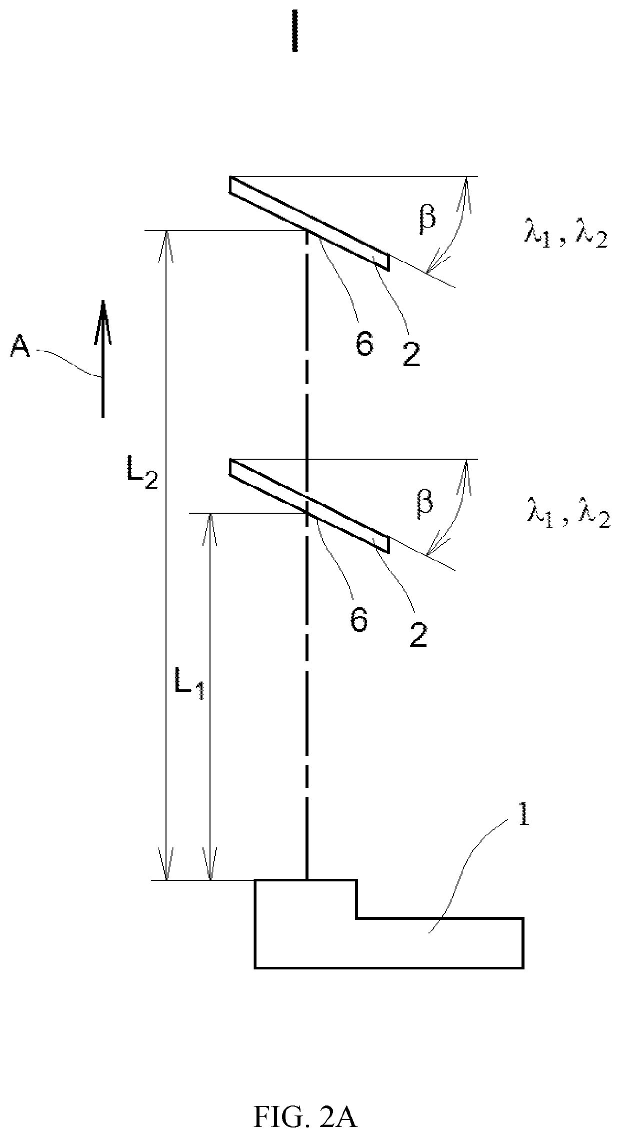
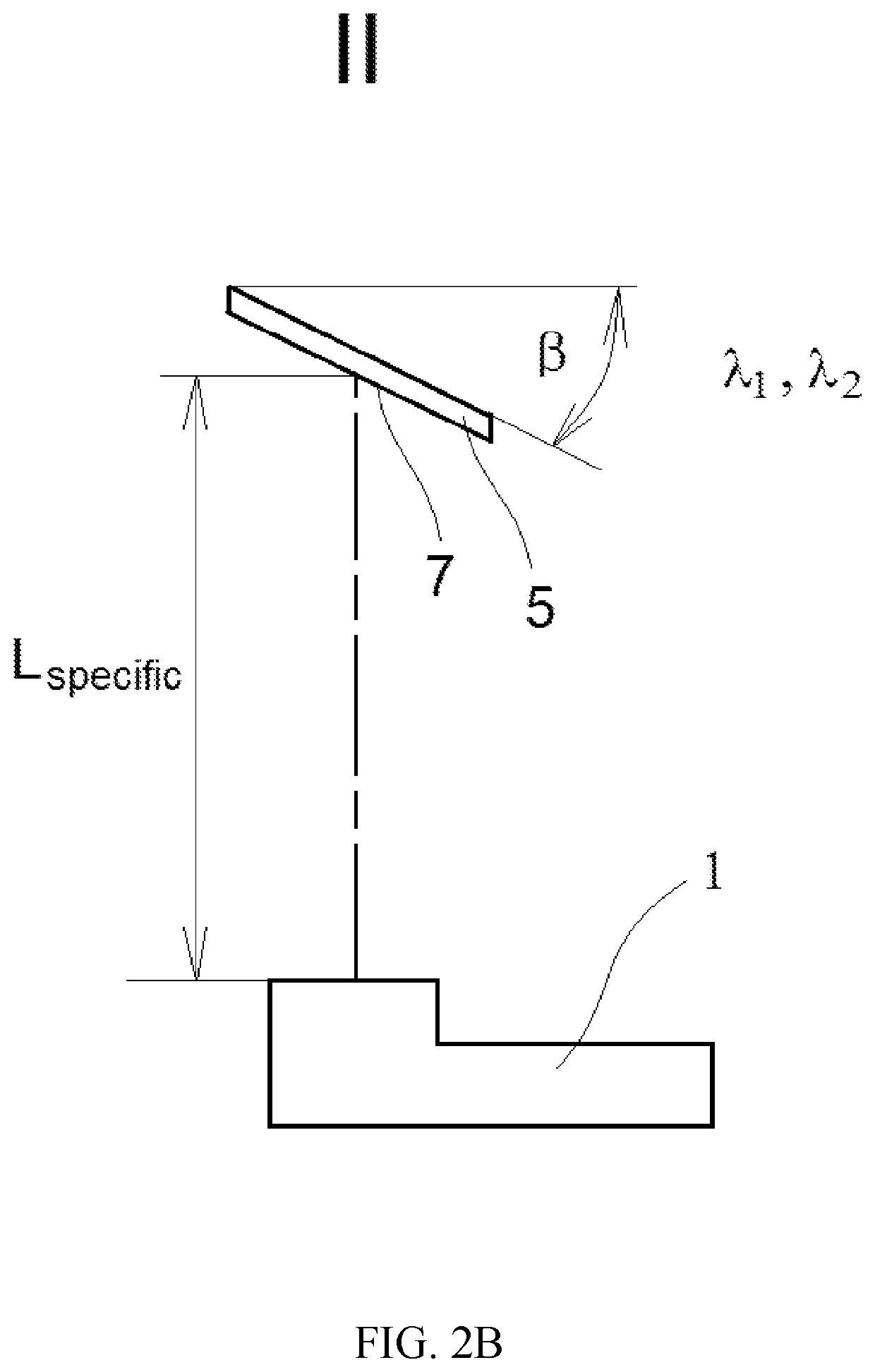
[0074]In this document the expressions “target material”, “reference material” and “sample material” are being used. The expression “target material” means a material of a surface to be monitored, for example the material of a road. The expression “reference material” means a material used in connection with calibration of the optical surface condition monitoring system as e.g. disclosed in connection with FIG. 2A. The material of the reference material and the material of the target material are typically different from each other. The expression “sample material” means a material used in connection with calibration of the optical surface condition monitoring system as e.g. disclosed in connection with FIG. 2B. Typically, a plurality of sample materials is used, for example old asphalt, new asphalt, etc.

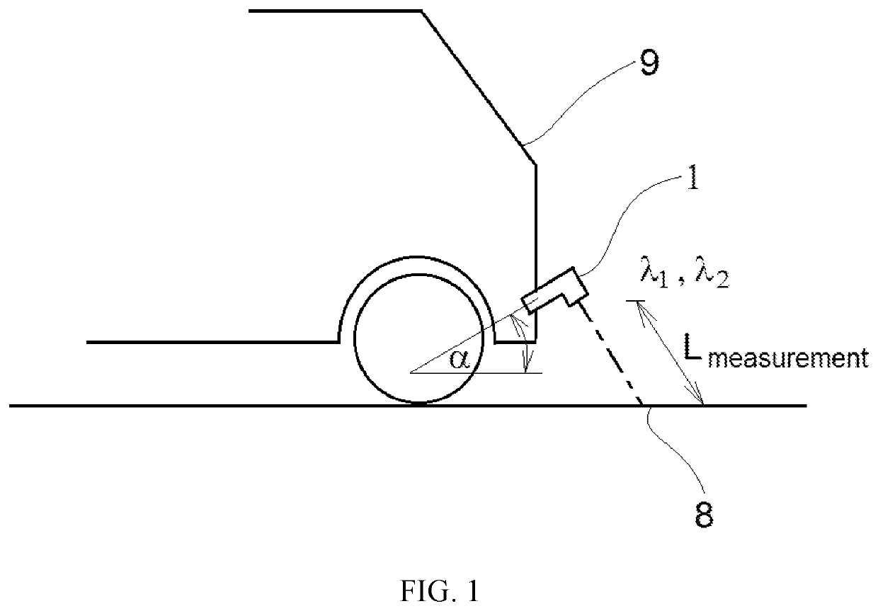
[0075]In FIG. 1 a schematic view of a commercially available optical surface condition monitoring system 1 is illustrated, wherein the optical surface condition monitoring system 1 ...


PUM


Abstract

A method and apparatus for calibrating an optical surface condition monitoring system (1). Light beams at different wavelengths (λ1, λ2) are emitted to a reference substrate (2) at different distances (L1, L2) as well as to sample substrates (5) at a specific distance (Lspecific). Subsequently, ratios between the signals scattered back from the reference substrate (2) and the signals scattered back from the sample substrates (5) are calculated. Then, input data regarding a measurement distance (Lmeasurement) between a target surface (8) to be monitored, for example a road, and the receiver (3) of the system (1) is provided. Further, a preset program is selected. Dry calibration of the system (1) can then take place based on the calculated ratios, the measurement distance (Lmeasurement) and the selected program. Dry calibration can be calculated without having to perform an actual dry calibration in the field and no dry calibration plate or dry spot of the target surface (8) is required.

Description

FIELD[0001]The present invention relates to a method of calibrating an optical surface condition monitoring system.[0002]Further, the present invention relates to an arrangement for calibrating an optical surface condition monitoring system.[0003]Furthermore, the present invention relates to an apparatus.[0004]Additionally, the present invention relates to a computer readable medium.BACKGROUND[0005]Surfaces which are located in an outdoor environment may be exposed to water, snow, ice or other material particles. Optical surface condition monitoring systems are capable of providing data relating to real-time surface condition information. An example of an optical surface condition monitoring system is a measurement system such as a road condition monitoring system. The systems are related to monitoring and maintenance of transportation infrastructure, such as highways, city streets, back roads and runways. The systems may be also used to allow evaluation and analysis to improve repa...

Claims


Application Information

Patent Timeline
Patent Type & Authority Patents(United States)
IPC IPC(8): B60W40/06G08G1/0967
CPCB60W40/06G08G1/096708B60W2555/00B60W2552/00G01N21/4785G01N21/31G01N21/4738G01N2021/3148G01N21/314G01N21/3554G01N21/01G01N21/25G01B11/0633G01J3/02G01N21/552
Inventor LAUKKANEN, SAMULIHYVÄTTINEN, TIMO
Owner VAISALA
Why Eureka
Try Eureka