Actuation device

a technology of actuation device and winding wire, which is applied in the direction of basic electric elements, coils, electrical apparatus, etc., can solve the problems of material weakening and winding wire tearout, and achieve the effect of improving the longevity of the actuation device and reliably preventing the damage of the winding wir

Active Publication Date: 2013-05-23
ETO MAGNETIC GMBH
View PDF3 Cites 3 Cited by
  • Summary
  • Abstract
  • Description
  • Claims
  • Application Information

AI Technical Summary

Benefits of technology

[0019]For further improving the longevity of the actuation device, it is preferred if the depression geometry is provided with a radius in at least one transition region, preferably in both transition regions to the contact element surface which is not depressed in relation to the depression geometry, in order to reliably prevent damage of the winding wire.

Problems solved by technology

This can in turn lead to a material weakening and in the extreme case to a tearing out of the winding wire.

Method used


Image

  • Actuation device
  • Actuation device
  • Actuation device

Examples


Embodiment Construction

[0043]In the figures, the same elements and elements with the same function are characterised with the same reference numbers.

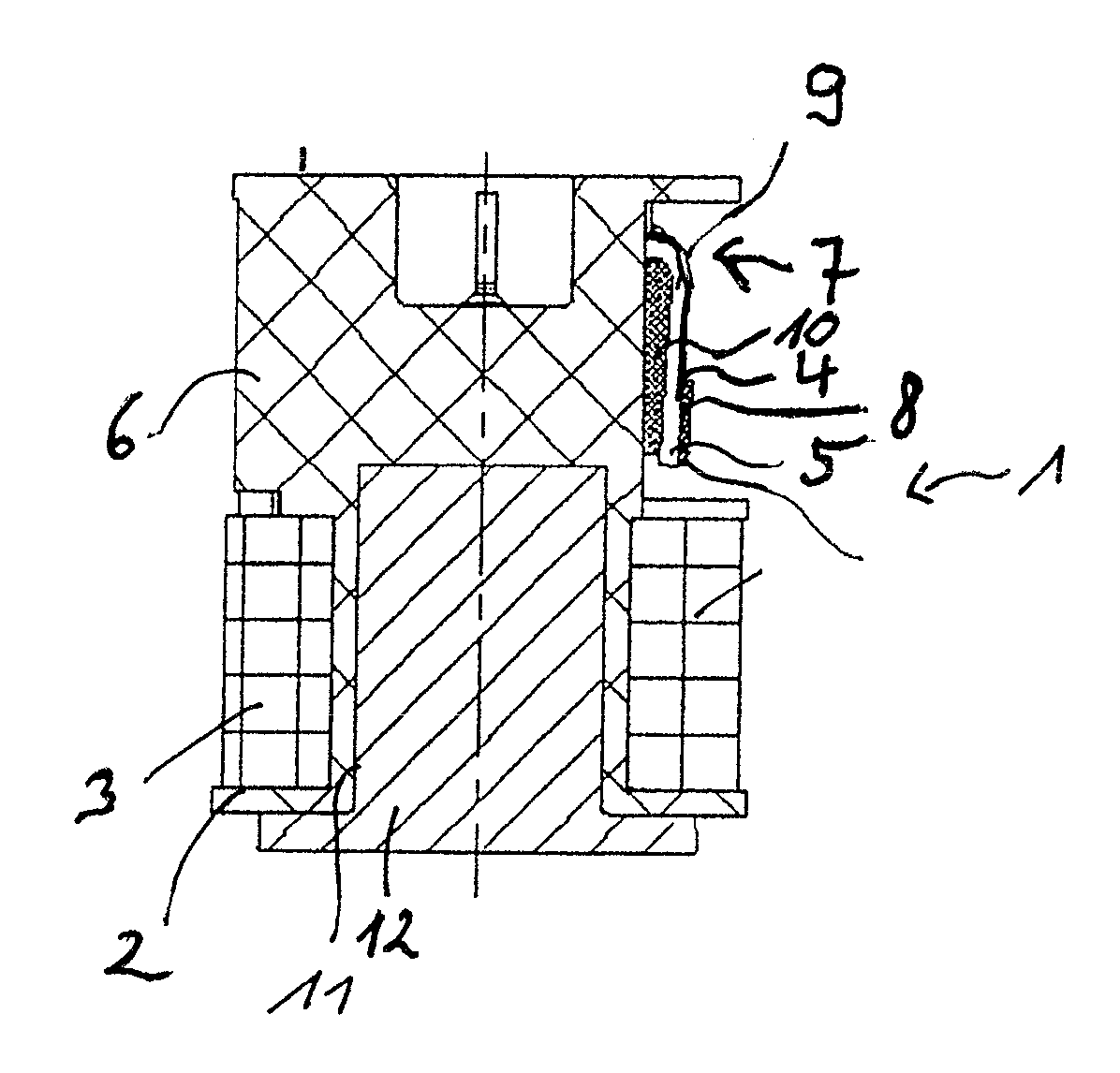
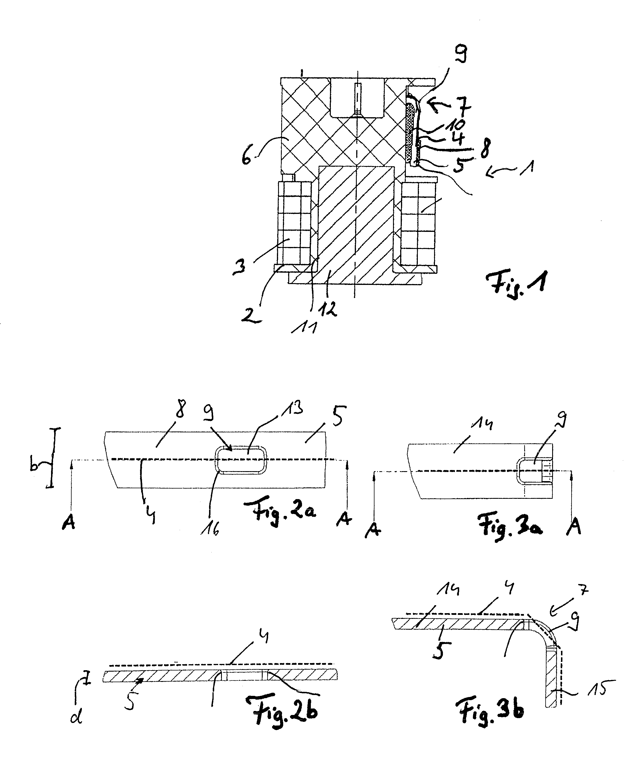
[0044]An electromagnetic actuation device 1 is shown in FIG. 1, which interacts in an actuating manner with an actuation partner, for example a camshaft hub shifting, which is not shown. The electromagnetic actuation device comprises a stator 2 with a coil winding 3, wherein an actuation element (armature) which is not illustrated is guided in an axially adjustable manner centrally in the interior of the actuator. To adjust the actuation element, current flows in the coil winding 3, more precisely the winding wire 4 thereof. To contact the winding wire 4, the same is electrically conductively connected at both ends to one tab-shaped contact element 5 in each case, which contact element is guided radially out of a support 6 constructed from plastic and bent by approximately 90° outside of the support 6 in a bending region 7. The winding wire runs on the contac...


PUM

PropertyMeasurementUnit
widthaaaaaaaaaa
widthaaaaaaaaaa
widthaaaaaaaaaa

Abstract

An electromagnetic actuation device with an actuation element, which can be adjusted relative to a stator on the basis of a magnetic actuation force which can be generated by the stator, wherein the stator has a coil winding, the winding wire of which is guided to a contact element bent at a bending region and is fixedly and electrically conductively connected to the same, wherein the contact element (5) has a depression geometry (9) in a bending region (7), which shortens a bending path of the winding wire (4) and through which the winding wire (4) passes.

Description

BACKGROUND OF THE INVENTION[0001]The invention relates to an electromagnetic actuation device with an in particular elongated actuation element which preferably has a permanent magnet means and can be adjusted relative to a stator on the basis of a magnetic actuation force which can be generated by the stator, wherein the stator has a coil winding, the winding wire of which is guided to a contact element bent at a bending region and is fixedly and electrically conductively connected to the same.[0002]Devices of this type have been known for a long time and are used for manifold purposes. The basic principle consists in a for the most part piston-like actuation element, which has an engagement region for the envisaged actuation task at the end, being guided in a generally magnetically conductive housing as armature between a stationary core region and a bearing element acting as yoke and being actuatable by means of an electromagnet (coil winding) provided in the core region for exam...

Claims


Application Information

Patent Timeline
Patent Type & Authority Applications(United States)
IPC IPC(8): H01F5/00
CPCH01F5/04H01F5/00H01F7/06
Inventor GOLZ, THOMAS
Owner ETO MAGNETIC GMBH
Why Eureka
Try Eureka